Crash attenuator apparatus

Active Publication Date: 2015-06-09
LINDSAY TRANSPORTATION SOLUTIONS LLC
View PDF12 Cites 17 Cited by
  • Summary
  • Abstract
  • Description
  • Claims
  • Application Information

AI Technical Summary

Benefits of technology

[0014]According to the invention, stabilizer structure is operatively associated with the track and with the supports stabilizing the supports in three planes to prevent tilting of the supports when the supports move along the track toward the backstop due to impact between the apparatus and a vehicle, whereby each of the collapsing tubes between adjacent supports will collapse substantially uniformly about the longitudinal axes thereof when compressed between said adjacent supports.

Problems solved by technology

This results in the tubes between adjacent supports collapsing substantially uniformly about the longitudinal axes of the tubes when compressed between adjacent supports.

Method used


Image

  • Crash attenuator apparatus
  • Crash attenuator apparatus
  • Crash attenuator apparatus

Examples


Embodiment Construction

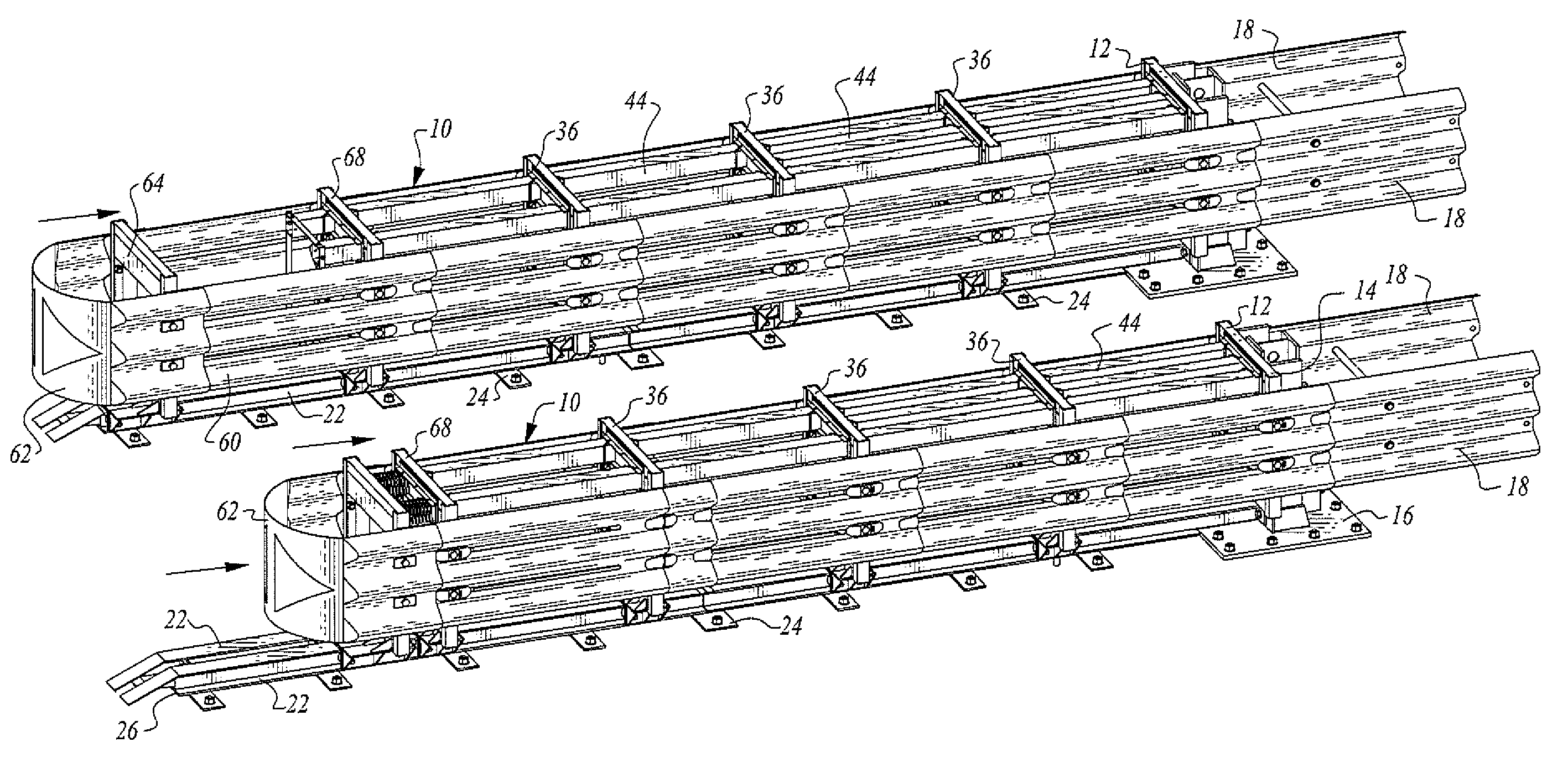
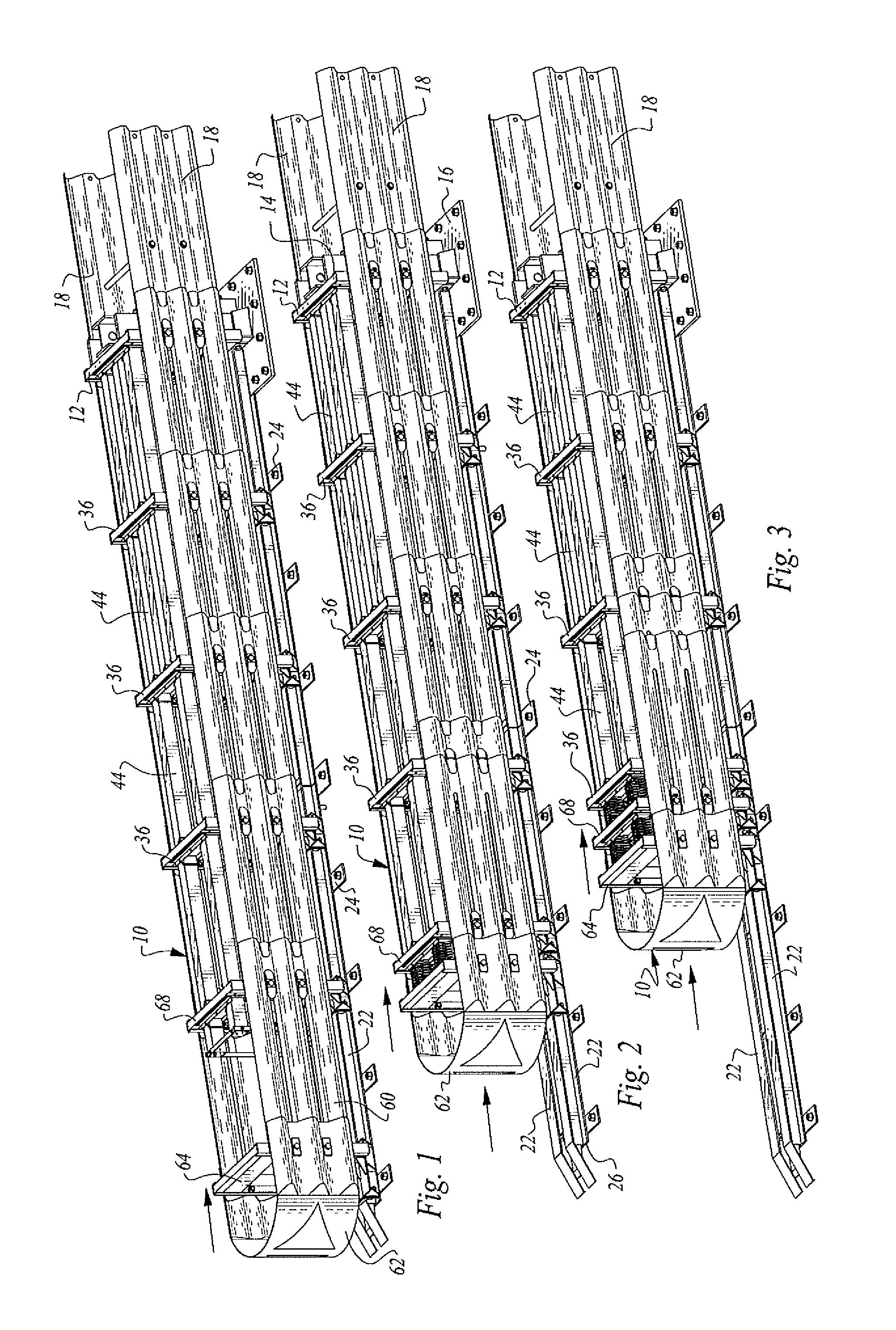
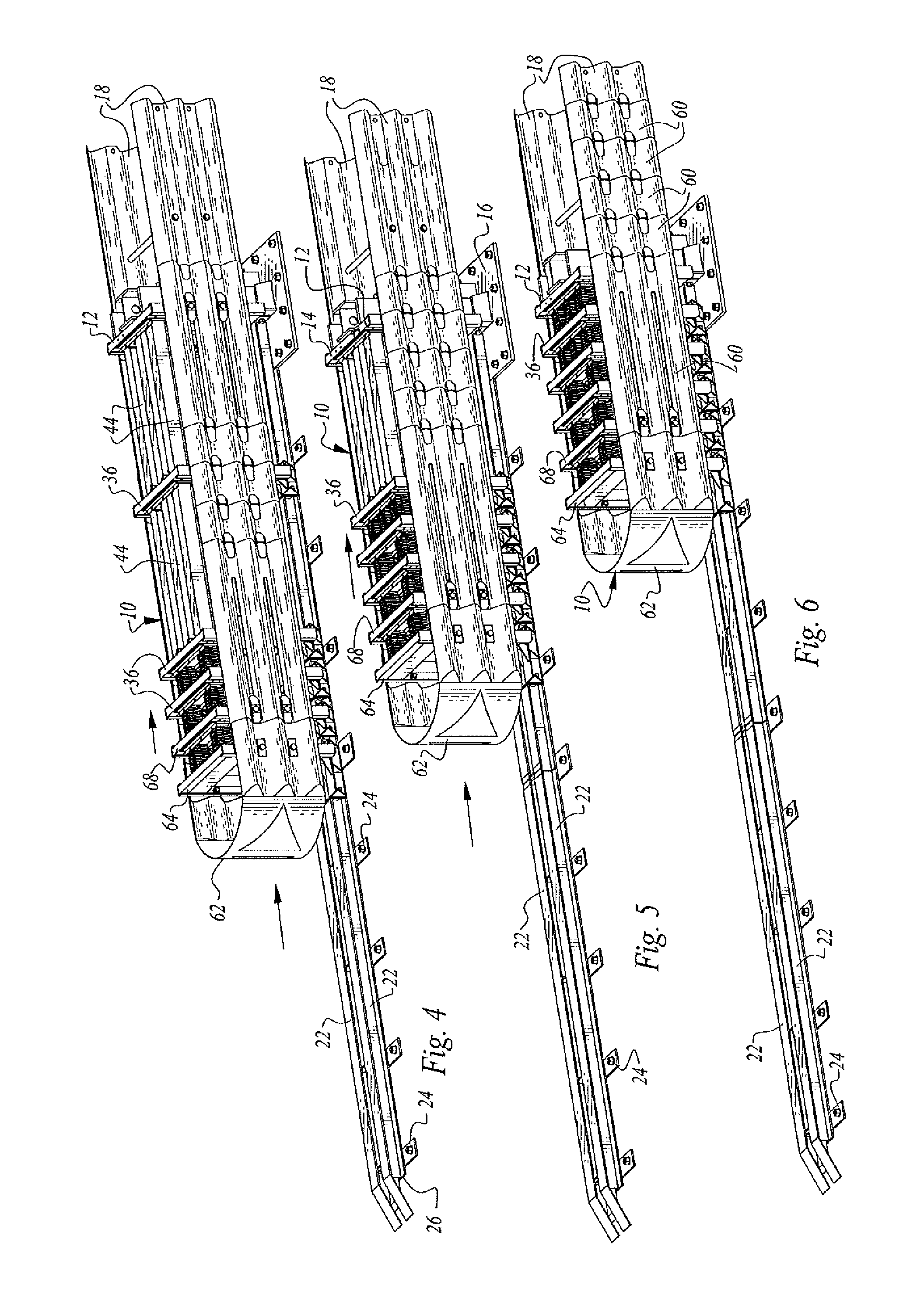
[0036]FIGS. 1-21 illustrate apparatus 10 constructed in accordance with the teachings of the present invention. The apparatus 10 is for absorbing energy when impacted by a vehicle. More specifically, the apparatus is utilized as a barrier which dissipates the energy of moving vehicles upon impact with an end of the apparatus.

[0037]Apparatus 10 includes a rigid backup structure 12 which is anchored to the ground. In the arrangement illustrated, the backup structure includes a backup structure frame 14 which extends upwardly from a base 16 fixedly secured to the ground by any suitable expedient such as anchor bolts.

[0038]In the disclosed embodiment, the backup structure frame 14 has side panels 18 secured thereto. The backup structure 12 may be located in front of a structure (not shown) to be protected thereby, such structure being, for example, pillars, bridge abutments, lighting poles, traffic side rails or dividers.

[0039]An elongated track including two parallel rails 22 extends a...


PUM


Abstract

Apparatus for absorbing energy when impacted by a vehicle includes a backstop structure, a track extending to the backstop structure, a plurality of collapsible tubes supported by spaced independently movable supports on the track, and stabilizer structure stabilizing the supports in three planes during movement of the supports on the track and collapse of the tubes.

Description

TECHNICAL FIELD[0001]This invention relates to apparatus for absorbing energy when impacted by a vehicle. More specifically, the apparatus is used as a barrier which dissipates the energy of moving vehicles upon impact with an end of the apparatus.BACKGROUND OF THE INVENTION[0002]It is well known to provide impact absorbing systems, often called “crash cushions” or “crash attenuators”, adjacent to rigid structures such as pillars, bridge abutments, lighting poles and the like for the purpose of absorbing vehicle impact energy and minimizing the effects of impact on the vehicle, the vehicle occupants and the structure being protected.[0003]There are many forms and types of energy absorption barriers.[0004]U.S. Pat. No. 5,851,005, issued Dec. 22, 1998, discloses an energy absorption barrier assembly including multiple pairs of ground engaging support uprights interconnected to one another by overlapping side panels. The side panels and uprights are connected together by inter-engaging...

Claims


Application Information

Patent Timeline
Patent Type & Authority Patents(United States)
IPC IPC(8): E01F15/14E01F15/04
CPCE01F15/146E01F15/0423E01F15/0461
Inventor ANGHILERI, MARCODI GIACOMO, VALERIAMAZZOLA, SILVIO
Owner LINDSAY TRANSPORTATION SOLUTIONS LLC
Why Eureka
Try Eureka