Metal seal

a technology of metal sealing and sealing plate, applied in the direction of mechanical equipment, drying machines, light and heating equipment, etc., can solve the problem that the sealing ability of the remaining straight portions may not be obtained insufficiently, and the sealing ability may not be tigh

Active Publication Date: 2015-06-16
MITSUBISHI CABLE IND LTD
View PDF3 Cites 0 Cited by
  • Summary
  • Abstract
  • Description
  • Claims
  • Application Information

AI Technical Summary

Benefits of technology

[0054]The present invention, as described above, characterized by that the cross-sectional configuration of the metal seal is ununiform for the entire periphery in the metal seal of which entire configuration is a closed ring, can improve the sealing ability as a whole by making the contact pressure uniform for the entire periphery.

Problems solved by technology

Especially, in case of non-circular having an R-shaped curved portion of extremely small radius of curvature, sufficient sealing ability (tight sealing ability) may not be obtained on remaining straight portions.

Method used


Image

  • Metal seal
  • Metal seal
  • Metal seal

Examples


second embodiment

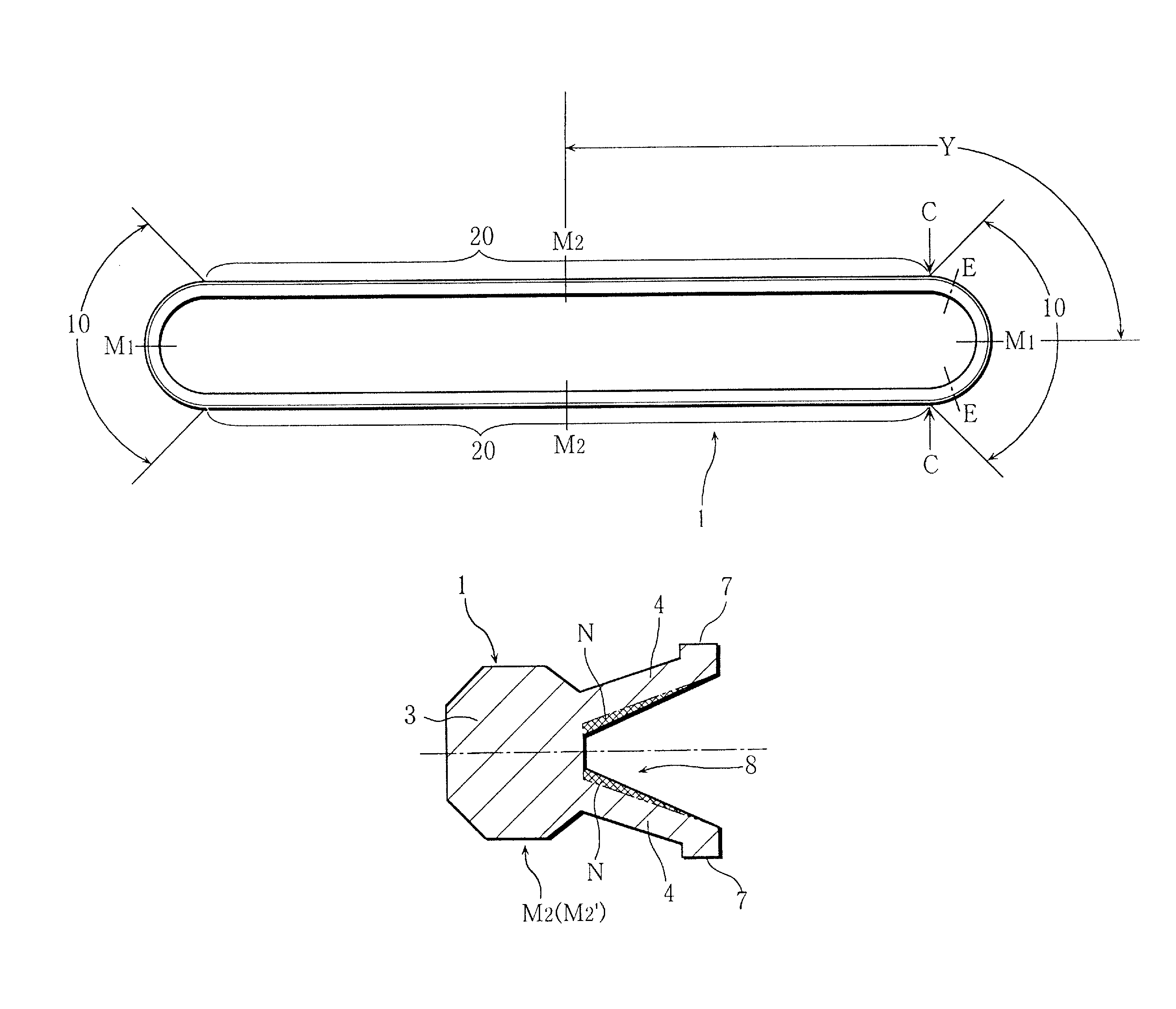
[0046]Next, to describe a second embodiment shown in FIG. 6 and FIGS. 7A through 7C, this metal seal 1 has a cross-sectional configuration called K-shaped, the base portion 3 (bottom wall portion) is approximately octagonal, and a pair of cantilever elastic leg pieces 4 are protruding from the base portion 3 as to open toward forth ends.

[0047]The small convex portion 7 for sealing on the forth end of the elastic leg piece 4 is attached to each of the facing flat faces 5 and 6. The small convex portion 7 may be formed small round shape and small triangular shape not shown in figures.

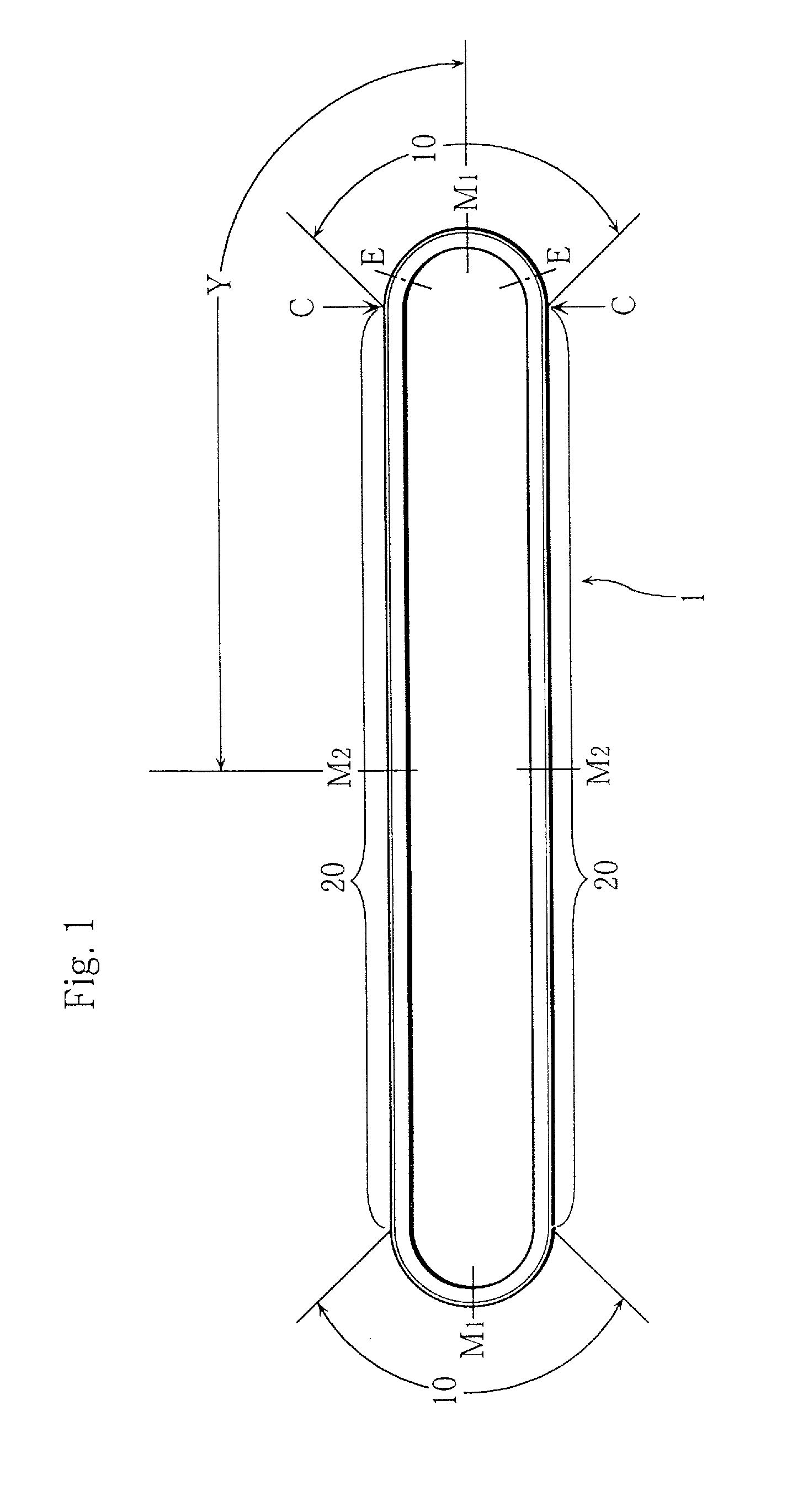
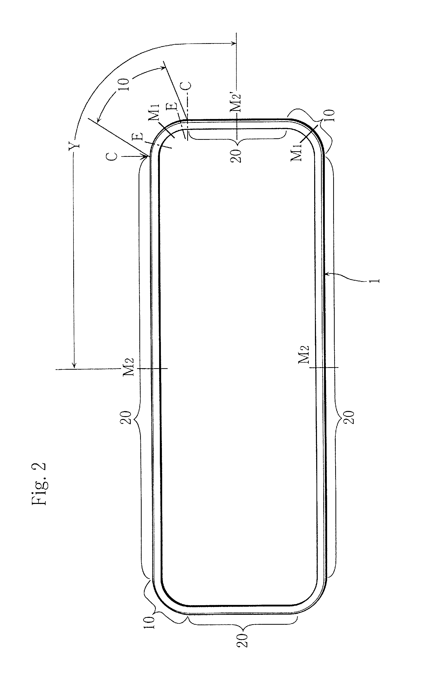
[0048]As clearly shown by comparison of FIG. 6 with FIG. 7A, the protruding dimension H of the elastic leg piece 4 is changed, and the protruding dimension H is set smaller on the center position M2 and the center position M2′ of the straight side portion 20 than on the center position M1 of the R-shaped curved portion 10 in the entire configuration shown in FIG. 1 or FIG. 2. Therefore, the flexural rigid...

third embodiment

[0051]Next, to describe a third embodiment shown in FIG. 8 and FIGS. 9A through 9C, this metal seal 1, having a cross-sectional configuration of laid U-shaped, is unitedly formed with the rather thick base portion (bottom wall portion) 3 and a pair of cantilever elastic leg pieces 4 protruding from the base portion 3 as to be parallel or opening toward forth ends. The small convex portion 7 for sealing of small triangle is formed on the forth end of the elastic leg piece 4.

[0052]FIGS. 9A, 9B, and 9C respectively correspond to FIGS. 5A, 5B, and 5C, or FIGS. 7A, 7B, and 7C, and, the protruding dimension H, the thickness dimension T, and the thickness N on leg piece base portion are similarly changed when compared with FIG. 8. The construction and function are similar to that of FIGS. 4 through 5C or FIGS. 6 through 7C.

[0053]The present invention, being modifiable, the entire configuration of the metal seal may be triangular, U-shaped, or inverted T-shaped. And, in FIG. 1 and FIG. 2, t...


PUM


Abstract

A metal seal of a non-circular ring which shows uniform sealing ability on whole periphery. The whole configuration of the metal seal is a non-circular ring having an R-shaped curved portion and a straight portion, and a cross-sectional configuration of the metal seal is changed as to make cantilever flexural rigidity larger on the straight portion than on the R-shaped curved portion.

Description

BACKGROUND OF THE INVENTION[0001]1. Field of the Invention[0002]This invention relates to a metal seal.[0003]2. Description of the Related Art[0004]Conventionally, a metal seal for sealing two parallel flat faces, of which cross-sectional configuration is U-shaped and whole configuration is circular, is known (refer to Japanese Provisional Publication No. 2009-24838).[0005]When the above-mentioned conventional metal seal is made non-circular as a whole and disposed along a window portion (opening portion) non-circular as a whole to seal the periphery of the non-circular window portion, total sealing ability may be decreased.[0006]Especially, in case of non-circular having an R-shaped curved portion of extremely small radius of curvature, sufficient sealing ability (tight sealing ability) may not be obtained on remaining straight portions.[0007]It is therefore an object of the present invention to provide a metal seal which shows a uniform sealing ability on the whole periphery.BRIEF...

Claims


Application Information

Patent Timeline
Patent Type & Authority Patents(United States)
IPC IPC(8): F16J15/10F16J15/08
CPCF16J15/08F16J15/0887F26B21/003F26B23/04F26B2200/16
Inventor TOHDOH, SATOSHI
Owner MITSUBISHI CABLE IND LTD
Why Eureka
Try Eureka