Connecting structure, connecting device and connecting method for electric wire and terminal, and wire harness

a technology of connecting device and connecting method, which is applied in the direction of connecting, contact member assembly/disassembly, and electric cable installation

a technology of connecting device and connecting method, which is applied in the direction of connecting, contact member assembly/disassembly, and electric cable installation

US9065261B2Active Publication Date: 2015-06-23FURUKAWA ELECTRIC CO LTD +1

Image

  • Connecting structure, connecting device and connecting method for electric wire and terminal, and wire harness
  • Connecting structure, connecting device and connecting method for electric wire and terminal, and wire harness
  • Connecting structure, connecting device and connecting method for electric wire and terminal, and wire harness

Examples


Embodiment Construction

[0060]Hereinafter, an embodiment of the present invention will be described in details with reference of the drawings.

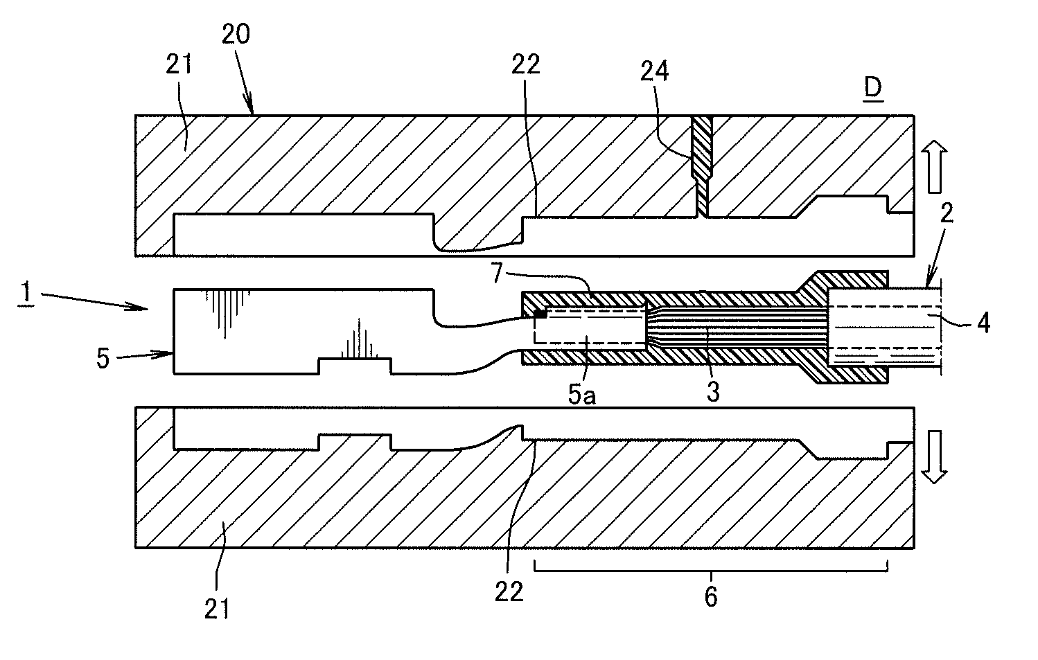
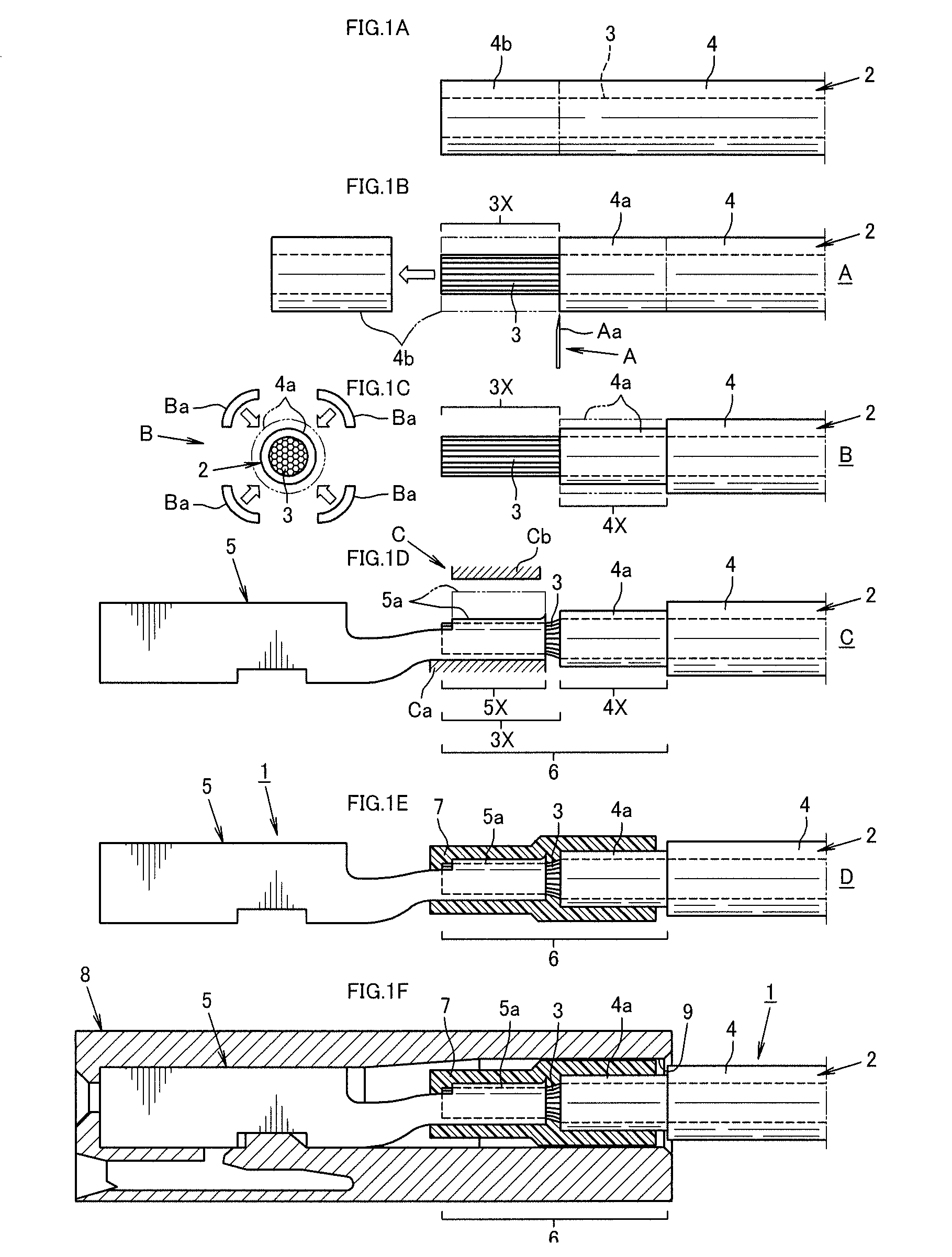
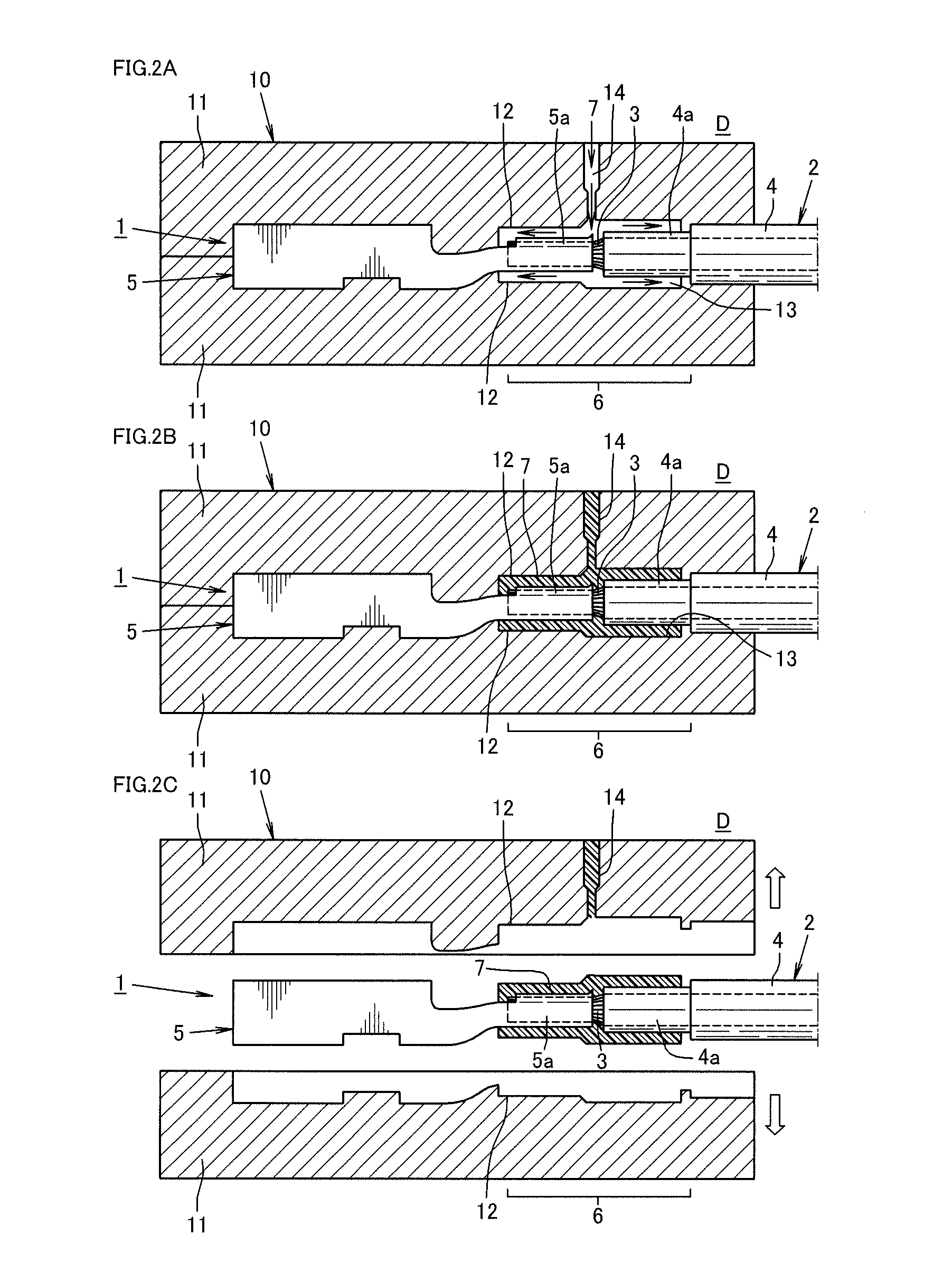
[0061]FIGS. 1A through 1F are process drawings showing a manufacturing method for a wire harness 1 in which an insulator 4 coated on an end portion of an electric wire 2 is subjected to diameter reduction and is cut off using a connecting device which will be described later. FIGS. 2A and 2B are process drawings showing a coating method for coating a connecting portion 6 with an insulating coating resin 7.

[0062]In the wire harness 1 of the present embodiment, an entire connecting portion 6 formed of a conductor exposed portion 3X of a conductor 3, which is exposed at an end portion of the electric wire 2, an insulator coated portion 4X, which is a portion adjacent to the conductor exposed portion 3X and is coated with the insulator 4, and a conductor crimping portion 5X of a terminal 5, which is crimped to the conductor 3 of the electric wire 2, is coated with the co...


PUM

PropertyMeasurementUnit
thicknessaaaaaaaaaa
diameteraaaaaaaaaa
lengthaaaaaaaaaa

Abstract

A connecting structure is applied for connecting an electric wire and a terminal. For coating a connecting portion of a conductor of the electric wire and the terminal, which form a wire harness, with a coating resin, a portion of an insulator, which is to be inserted into a terminal insertion hole of a connector housing, is subjected to a diameter reduction process such that an outer diameter of the coating resin coated on the insulator is smaller than the terminal insertion hole.

Description

TECHNICAL FIELD[0001]The present invention relates to a connecting structure, a connecting device and a connecting method for electric wires and terminals, and a wire harness which prevent corrosion in connecting portions of electric wire conductors and terminals.BACKGROUND ART[0002]As a method for preventing corrosion (hereinafter, referred to as “anti-corrosion”) in connecting portions between electric wire conductors and terminals to which the conductors are connected as mentioned above, a waterproof method and water proof device for end connecting portions of coated electric wires (see Patent Document 1) has been proposed, for example.[0003]More specifically, in the method and the device of Patent Document 1, an end connecting portion where a conductor of a coated electric wire and a terminal metal fitting are connected is set in a cavity of a shaping die, and a side opening of the cavity from which the coated electric wire is drawn outside is blocked with an elastic baffle plat...

Claims


Application Information

Patent Timeline
23 Jun 2015
Publication
US9065261B2
IPC
H02G3/04; H01R43/24; H01R4/18; H02G1/00
CPC
H02G3/0406; H01R4/183; H01R43/24; H01R4/18; H02G1/00; Y10T29/49117
Inventors
KAWAMURA, YUKIHIRO; TAKAMURA, SATOSHI