Illuminated chamber status indicator

a status indicator and illumination chamber technology, applied in the direction of weapons, ammunition loading, weapon components, etc., can solve the problems of limiting the ability of all other chamber-loaded indicators to fulfill their intended purpose, the risk of not immediately knowing the status of weapons can be deadly, and the claim of tactile confirmation by all other chamber-loaded indicators is nearly impossible for those that do or must wear hand protection

Active Publication Date: 2015-06-30
ADVANCED COMBAT SOLUTIONS INC
View PDF29 Cites 13 Cited by
  • Summary
  • Abstract
  • Description
  • Claims
  • Application Information

AI Technical Summary

Benefits of technology

[0027]Available in extremely tiny glass vials hermetically sealed, making them versatile as an embeddable component into an existing firearms assembly or mechanism such as a chamber loaded indicator, creating the new object, an ICSI
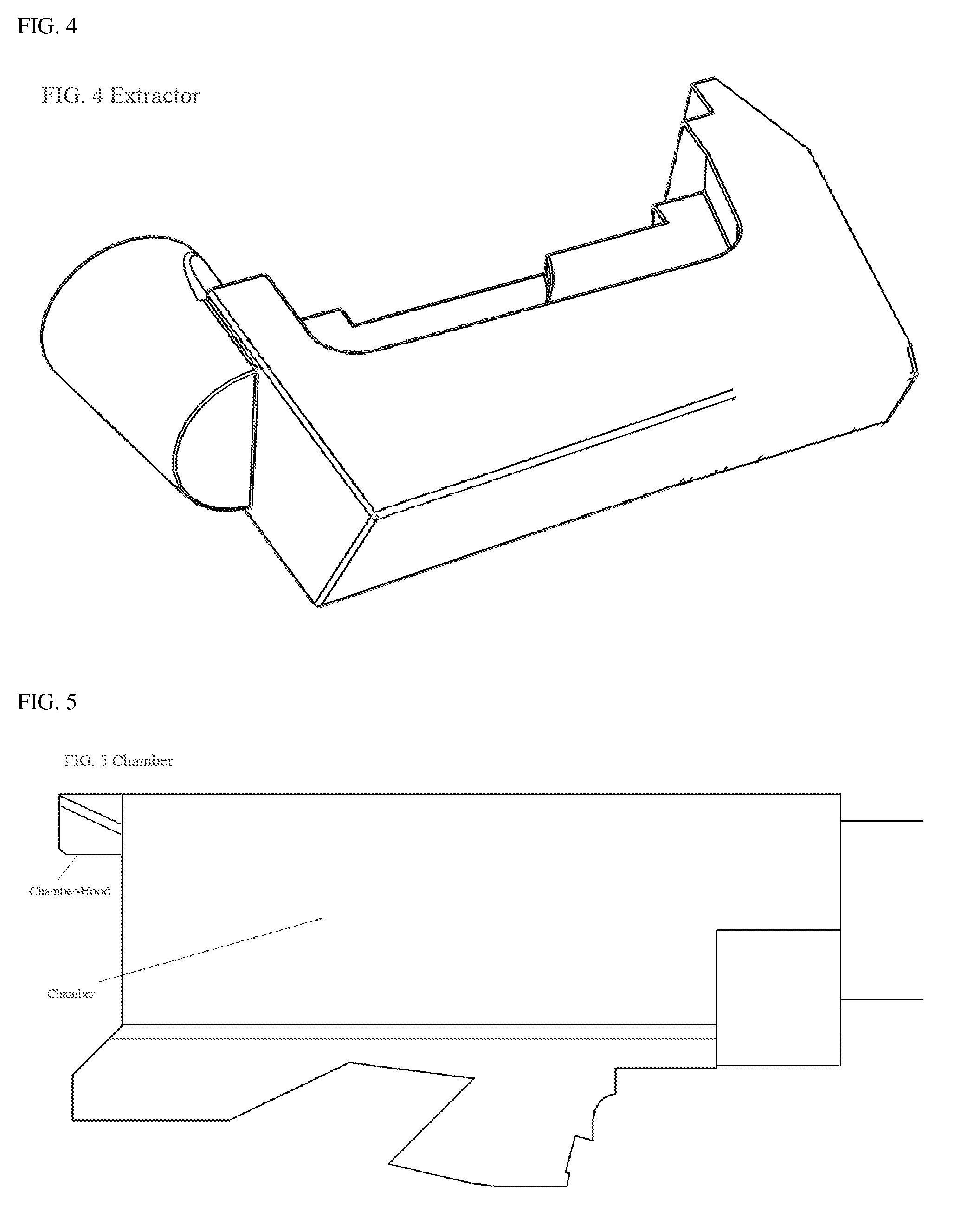
[0033]This invention provides a never before conceived self-illuminated chamber status indicator (ICSI) utilizing GTLS. The GTLS is embedded into a chamber status indicator component and / or mechanism(s) creating the present invention called, the Illuminated Chamber Status Indicator (ICSI). The introduction of GTLS as an embedded component to the chamber status indicator mechanism creates a self illuminated chamber status indicator, or simply an illuminated chamber status indicator (ICSI). The ICSI, allows the operator of the firearm to check the status of the weapon, loaded or unloaded, in very low light to zero light conditions. The ICSI visually signals the presence of a live round of ammunition and / or cartridge, or shell casing only in the chamber of the firearm. The ICSI accomplishes this visual confirmation of weapon status (loaded), by exposing the self-illuminated part, specifically the tritium to the firearms operator. If the weapon status is unloaded, the ICSI, specifically the light being emitted from the tritium will not be visible to the firearms operator.

Problems solved by technology

The risk of not immediately knowing the status of the weapon can be lethal for the aforementioned groups, as combat readiness is a requisite of their job responsibilities.
Unfortunately, the hours of operation for war or policing activities do not only take place between the hours of 8:00 am to 5:00 pm, or solely located on a shooting range.
This further limits the ability of all other chamber-loaded indicators to fulfill their intended purpose.
Therefore, this claimed tactile confirmation by all other chamber-loaded indicators is nearly impossible for those that do or must wear hand protection in the course of their work.
It is the case for firearms such as Springfield Armory's XD handgun including the XDm models, the difference in degrees by which the chamber-loaded indicator protrudes in loaded or unloaded state is minor, and is not quickly ascertainable either visually or tactilely.
However, their chamber-loaded indicator devices on all of their models are extremely difficult to confirm visually even in lighted conditions and would be virtually impossible to confirm if the operator's hands were covered with gloves.

Method used


Image

  • Illuminated chamber status indicator
  • Illuminated chamber status indicator
  • Illuminated chamber status indicator

Examples


Embodiment Construction

[0050][How it is Applied in Firearms]

[0051]The ICSI technology is designed to be, and can be applied universally to all makes and models of firearms. This encompasses handguns, rifles, and shotguns. Although these categories of firearms fulfill very different roles as well as have different external structures, they also share much of the same design of internal components.

[0052][Existing Firearms—Common Design Features]

[0053]Categories of firearms relevant to the ICSI invention include the following;[0054]Handgun—semi-automatic, single shot, full automatic (select-fire), and revolver[0055]Rifle—semi-automatic, bolt action single shot, full automatic (select-fire)[0056]Shotgun—pump action, semi-automatic and full automatic (select-fire)

[0057][Modern Firearm Ammunition—these Cartridge Components Will be Referred to Henceforth]

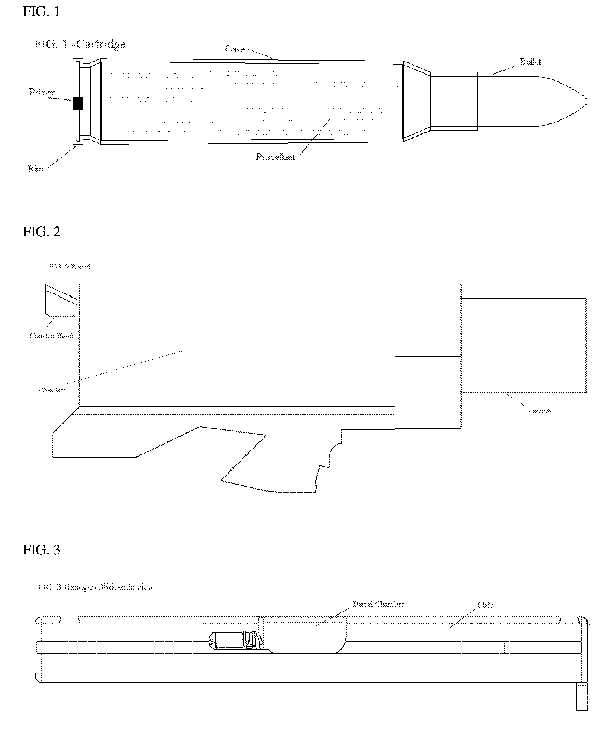
[0058]Cartridge based ammunition has been in popular use since the mid-1800s. Although the ICSI invention could be applied to non-modern firearms, it is the int...


PUM


Abstract

A chamber status indicator for a firearm such as a handgun, rifle, or shotgun is disclosed. The chamber status indicator comprises a self-illuminating substance such as a gaseous tritium light source or self-illuminating paint, wherein light from the self-illuminating substance is visible only when a cartridge is loaded in the chamber. The self-illuminating substance can be mounted in a mechanical chamber status indicator. The self-illuminating substance can be mounted in a wall of the chamber. The self-illuminating substance can be mounted in a cartridge extractor. The self-illuminating substance can be affixed to or integrated into a bolt, breech or slide of the firearm. The self-illuminating substance can be integrated into a cylinder containing multiple chambers.

Description

CROSS-REFERENCE TO RELATED APPLICATIONS[0001]This application claims the benefit of Provisional Patent Application Ser. No. 61 / 443,060, filed 2011 Feb. 15 by the present inventor.STATEMENT REGARDING FEDERALLY SPONSORED RESEARCH OR DEVELOPMENT[0002]Not applicable.NAMES OF THE PARTIES TO A JOINT RESEARCH AGREEMENT[0003]Not applicable.SEQUENCE LISTING[0004]Not applicable.BACKGROUND OF THE INVENTION[0005]The following is a tabulation of some prior art that presently appears relevant:[0006]U.S. Pat.Patent NumberFile DateIssue DatePatentee5,410,831Aug. 22, 1994May 2, 1995Felk, Edward K.5,926,987Aug. 8, 1997Jul. 27, 1999Novak, Peter8,109,023Feb. 16, 2010Feb. 7, 2012Pikielny, Dov6,094,850May 24, 1996Aug. 1, 2000Villani, Michael J.6,256,915Dec. 28, 1999Jul. 10, 2001da Silveira, Nilton6,622,411Aug. 29, 2002Sep. 23, 2003Lienbenberg, Paul6,785,994Jun. 17, 2003Sep. 7, 2004Christiansen, Ned F.6,857,213Dec. 3, 2003Feb. 22, 2005Fluhr, Norbert4,539,889Dec. 30, 1982Sep. 10, 1985Clock, Gaston[0007]A c...

Claims


Application Information

Patent Timeline
Patent Type & Authority Patents(United States)
IPC IPC(8): F41A9/53
CPCF41A9/53
Inventor BALL, MICHAEL LEROY
Owner ADVANCED COMBAT SOLUTIONS INC
Why Eureka
Try Eureka