Lifting mechanism and electronic device therewith

a technology of electronic devices and lifting mechanisms, which is applied in the direction of portable computers, instruments, computing, etc., can solve the problems of inability to get a sufficient gap between the notebook computer and the holding surface, the size of the rubber foot cushion cannot be enlarged in consideration of structural strength, and the inability to contain inside the notebook computer casing, etc., to achieve convenient carrying or containing of the electronic device, increase the gap, and the effect of comfortable angl

Inactive Publication Date: 2015-06-30
WISTRON CORP
View PDF1 Cites 2 Cited by
  • Summary
  • Abstract
  • Description
  • Claims
  • Application Information

AI Technical Summary

Benefits of technology

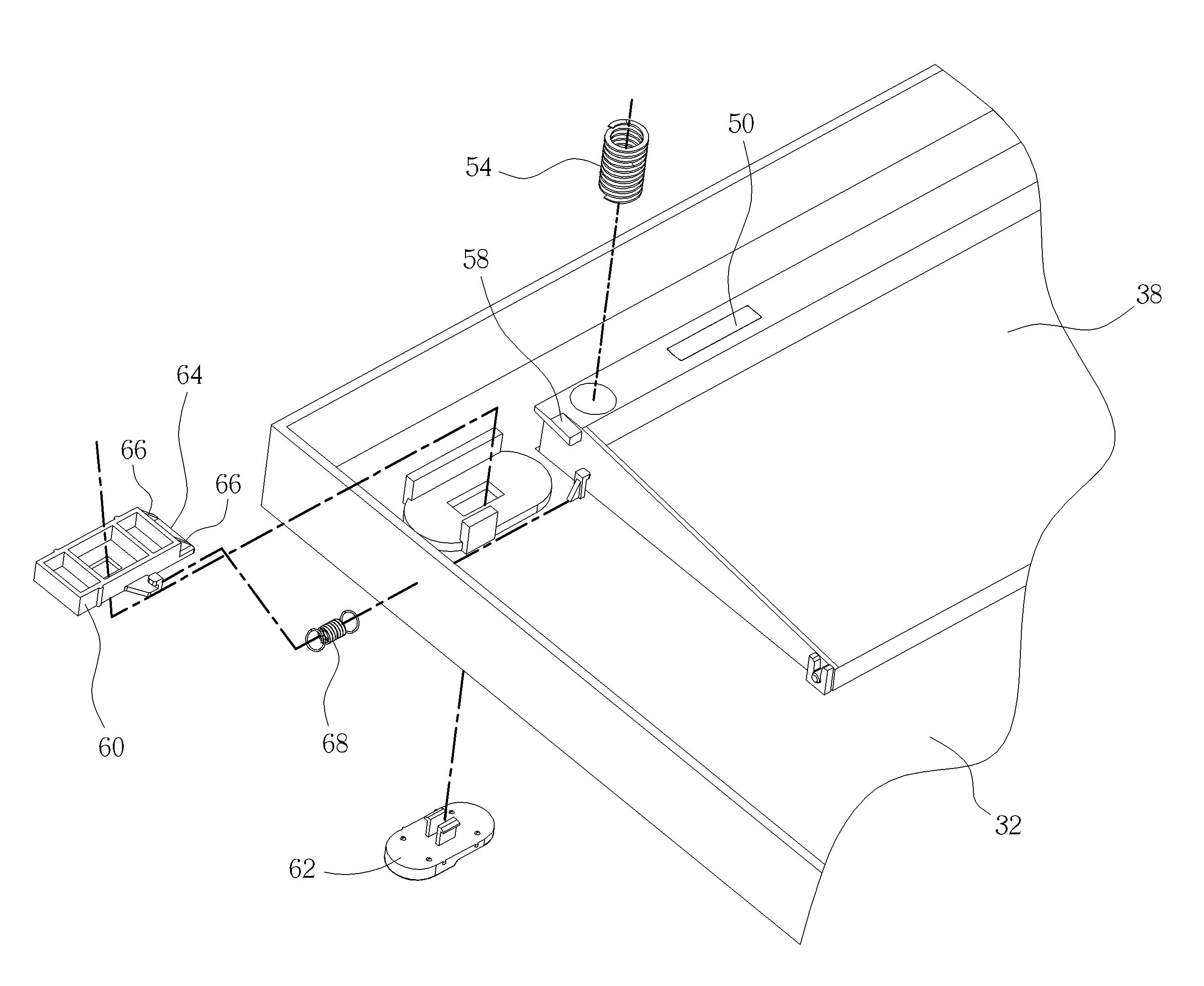
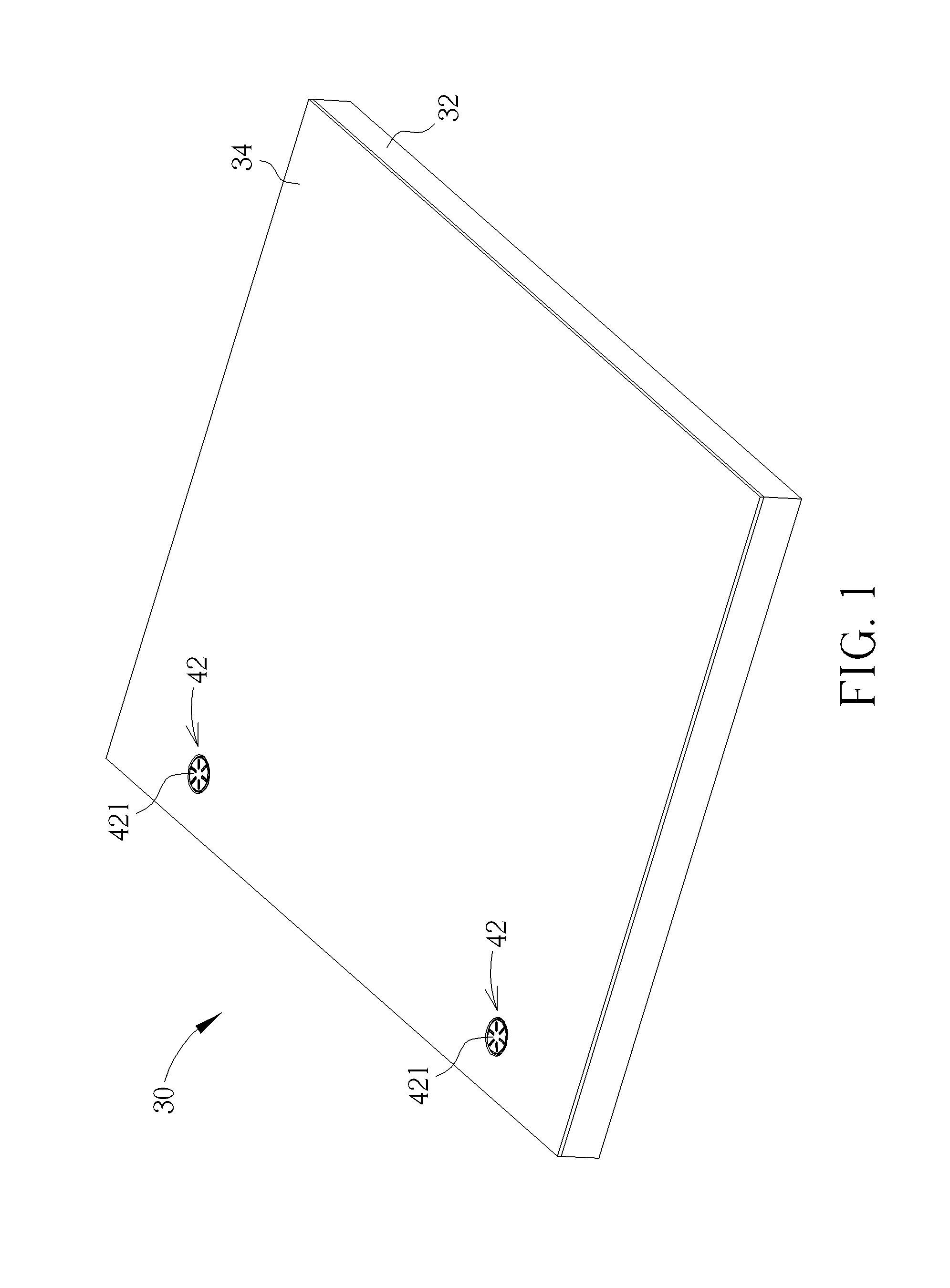
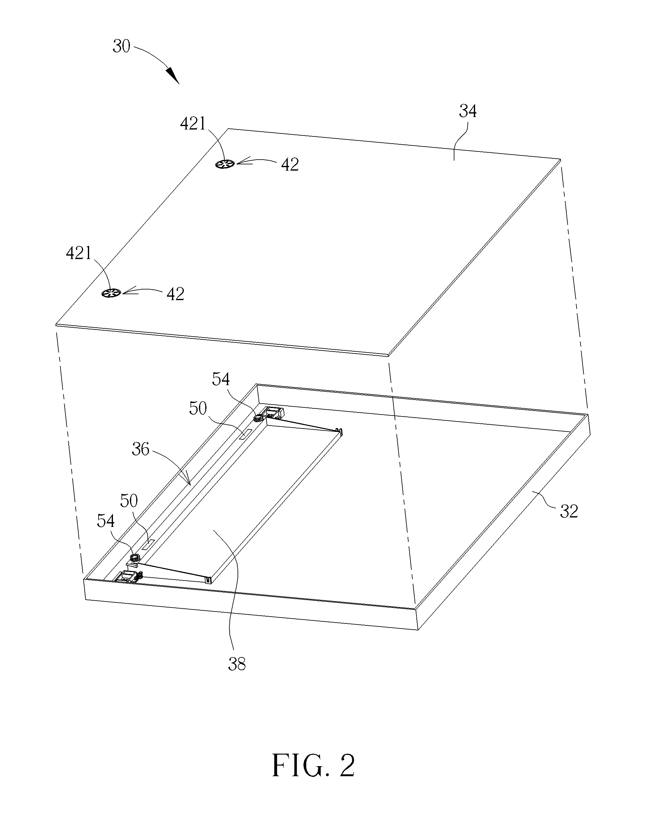
[0018]In summary, the present invention utilizes the first magnetic member, the second magnetic member and the resilient member to retract the lifting member inside the first casing or expanding the lifting member to be out of the first casing. When the second magnetic member is rotated with the rotating arm to the position where the second magnetic member is aligned with the first magnetic member, the magnetic force generated between the first magnetic member and the second magnetic member is used for retracting the lifting member inside the first casing, so that the electronic device is facilitated to carry or contain. In addition, when the second magnetic member is rotated with the rotating arm to the position where the second magnetic member is not aligned with the first magnetic member, the resilient member resiliently pushes the lifting member, so as to drive the lifting member to be expanded out of the first casing. As a result, it can further lift the first casing and the second casing of the electronic device.
[0019]Furthermore, when the electronic device utilizes the lifting member as a supporter, the lifting member can be thickened practically, so as to increase a gap between the electronic device and a holding surface. Accordingly, it provides the user with a comfortable angle when the electronic device is in use. As a result, it greatly increases flexibility of implementation, convenience and comfort of the electronic device in use.

Problems solved by technology

Since the rubber foot cushion is fixed on the bottom of the notebook computer, it cannot be contained inside a casing of the notebook computer.
Furthermore, the size of the rubber foot cushion cannot be enlarged in consideration of structural strength.
Accordingly, when the notebook computer utilizes the rubber foot cushion as a supporter, it is not attainable to get a sufficient gap between the notebook computer and the holding surface due to constraint of the size of the rubber foot cushion.
As a result, it greatly reduces flexibility of implementation, convenience and comfort of the notebook computer in use.

Method used


Image

  • Lifting mechanism and electronic device therewith
  • Lifting mechanism and electronic device therewith
  • Lifting mechanism and electronic device therewith

Examples


Embodiment Construction

[0034]In the following detailed description of the embodiments, reference is made to the accompanying drawings which form a part hereof, and in which is shown by way of illustration specific embodiments in which the invention may be practiced. In this regard, directional terminology, such as “top,”“bottom,” etc., is used with reference to the orientation of the Figure(s) being described. The components of the present invention can be positioned in a number of different orientations. As such, the directional terminology is used for purposes of illustration and is in no way limiting. On the other hand, the drawings are only schematic and the sizes of components may be exaggerated for clarity. It is to be understood that other embodiments may be utilized and structural changes may be made without departing from the scope of the present invention. Also, it is to be understood that the phraseology and terminology used herein is for the purpose of description and should not be regarded as...


PUM


Abstract

A lifting mechanism includes a lifting member, a first magnetic member, a rotating arm, a second magnetic member and a resilient member. The lifting member is pivoted to a first casing. The first magnetic member is fixed on the lifting member. The rotating arm is pivoted to a second casing. The second magnetic member is fixed on the rotating arm for attracting the first magnetic member as being rotated with the rotating arm to where the second magnetic member is aligned with the first magnetic member, so as to retract the lifting member inside the first casing. The resilient member resiliently abuts against the second casing and the lifting member for pushing the lifting member as being rotated with the rotating arm to where the second magnetic member is not aligned with the first magnetic member, so as to expand the lifting member out of the first casing.

Description

BACKGROUND OF THE INVENTION[0001]1. Field of the Invention[0002]The present invention relates to a lifting mechanism and an electronic device, and more particularly, to a lifting mechanism with retractable function and an electronic device therewith.[0003]2. Description of the Prior Art[0004]Recently, a notebook computer has been widely implemented in human's daily life due to its portability. Conventionally, a rubber foot cushion is utilized for supporting the notebook computer on a holding surface, such as a desk. Since the rubber foot cushion is fixed on the bottom of the notebook computer, it cannot be contained inside a casing of the notebook computer. Furthermore, the size of the rubber foot cushion cannot be enlarged in consideration of structural strength. Accordingly, when the notebook computer utilizes the rubber foot cushion as a supporter, it is not attainable to get a sufficient gap between the notebook computer and the holding surface due to constraint of the size of t...

Claims


Application Information

Patent Timeline
Patent Type & Authority Patents(United States)
IPC IPC(8): G06F1/16
CPCG06F1/166Y10T74/18304
Inventor LEE, JIA-HUNGKAO, SAN-PAOCHUANG, CHENG-HSIANG
Owner WISTRON CORP
Why Eureka
Try Eureka