Liquid ejection head and inkjet printing apparatus

a technology of inkjet printing and ejection head, which is applied in the direction of printing, etc., can solve the problems of increased power required for increased energy consumption, and inefficient use of the bubbles generated by driving the heat-generating element for ejection of ink, so as to achieve the effect of ejecting ink more efficiently

Active Publication Date: 2015-07-21
CANON KK
View PDF6 Cites 6 Cited by
  • Summary
  • Abstract
  • Description
  • Claims
  • Application Information

AI Technical Summary

Benefits of technology

[0008]Therefore, in view of the above-described circumstances, an object of the present invention is to provide a liquid ejection head capable of ejecting ink more efficiently and an inkjet printing apparatus.
[0015]According to the present invention, it is possible to efficiently eject ink with a small amount of energy consumption, and thus it is possible to suppress power consumption to be small. Because of this, it is possible to provide a liquid ejection head, the running cost of which is reduced. Furthermore, it is possible to efficiently use energy consumed by a heat-generating element for ejection of ink, and thus the heat-generating element can be downsized. Consequently, it is possible to provide a downsized liquid ejection head and at the same time, to reduce the manufacturing cost of the liquid ejection head. In addition, it is possible to provide an inkjet printing apparatus, the running cost of which is suppressed to be low.

Problems solved by technology

Therefore, there is a possibility that power required for driving the heat-generating element is increased and energy consumption is increased.
Therefore, depending on the position of the block arranged around the heat-generating element, there is a possibility that bubbles generated by driving the heat-generating element are not used efficiently for ejection of ink.
Due to this, there is a possibility that it is necessary to generate a larger amount of heat by the heat-generating element in order to eject ink, and thus the amount of power consumption increases and the running cost rises.
Furthermore, the size of the heat-generating element used for ejection of ink is increased, and thus there is a possibility that the liquid ejection head becomes large and at the same time, the manufacturing cost of the liquid ejection head rises.

Method used


Image

  • Liquid ejection head and inkjet printing apparatus
  • Liquid ejection head and inkjet printing apparatus
  • Liquid ejection head and inkjet printing apparatus

Examples


Embodiment Construction

[0026]Hereinafter, an inkjet printing apparatus and a liquid ejection head according to an embodiment of the present invention will be explained with reference to the drawings.

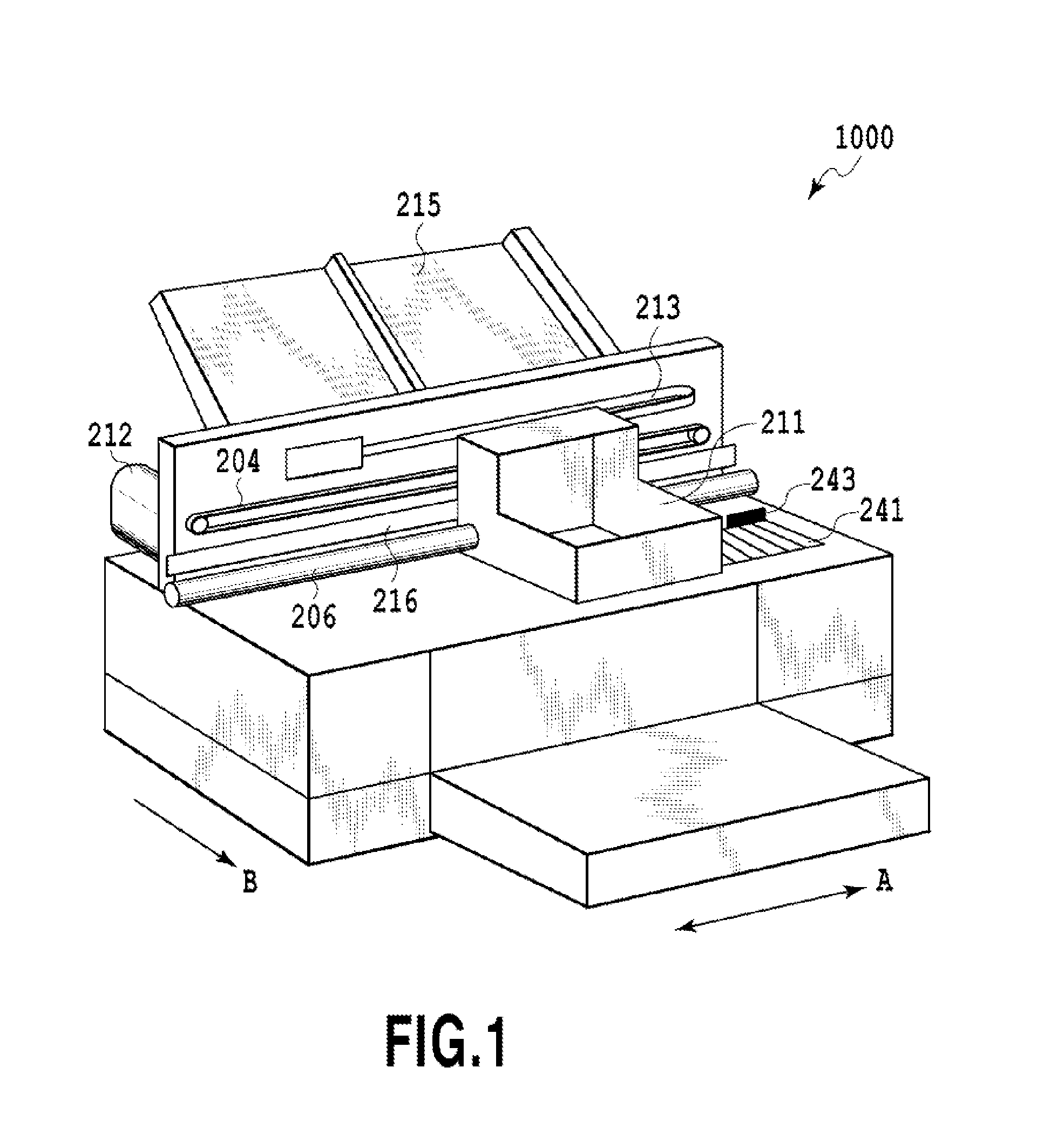
[0027]FIG. 1 is a perspective view of an inkjet printing apparatus 1000 according to the embodiment of the present invention. The inkjet printing apparatus 1000 shown in FIG. 1 includes a carriage 211 in which a liquid ejection head unit 410 as an inkjet liquid ejection head is mounted. In the inkjet printing apparatus 1000 of the present embodiment, the carriage 211 is guided so as to be capable of moving in the main scanning direction of an arrow A along a guide shaft 206. The guide shaft 206 is arranged so as to extend along the width direction of a print medium. Consequently, the liquid ejection head mounted in the carriage 211 performs printing while scanning in a direction intersecting a conveyance direction in which the print medium is conveyed. As described above, the inkjet printing apparatus 1000 is ...


PUM


Abstract

A liquid ejection head capable of more efficiently ejecting ink and an inkjet printing apparatus are provided. The liquid ejection head has a block member which surrounds at least a part of an effective bubble-generating region involved with heat generation in a heat-generating element and which is formed so as to protrude from the heat-generating element in a direction in which a liquid is ejected. The block member is arranged in a position where a distance of a position of an inner end part from an outer end part of the effective bubble-generating region is +2 μm or less, with an outward direction being set to be positive.

Description

BACKGROUND OF THE INVENTION[0001]1. Field of the Invention[0002]The present invention relates to a liquid ejection head configured to heat a liquid by a heat-generating element and to eject the liquid through an ejection port, and an inkjet printing apparatus.[0003]2. Description of the Related Art[0004]The inkjet printing apparatus includes a thermal inkjet system in which ink is heated by driving a heat-generating element arranged inside a liquid ejection head and bubbles are generated within the ink, thereby ink droplets being ejected through an ejection port.[0005]In the liquid ejection head in the inkjet printing apparatus of thermal inkjet system, in the case where bubbles are generated by driving the heat-generating element in order to eject ink droplets, a backflow of ink may be caused inside the ink flow passage of the liquid ejection head due to generation of bubbles. In the case where the backflow of ink is caused, the pressure increased by generation of bubbles is reduce...

Claims


Application Information

Patent Timeline
Patent Type & Authority Patents(United States)
IPC IPC(8): B41J2/05B41J2/14
CPCB41J2/14145B41J2/1404B41J2/14129
Inventor NAKAGAWA, YOSHIYUKIAOKI, TAKATSUNAYAMADA, KAZUHIROKOMAMIYA, YUMIKASAI, RYO
Owner CANON KK
Why Eureka
Try Eureka