
Software defined radio device and configuration method of the same

a software defined radio and configuration method technology, applied in the direction of transmission, electrical equipment, etc., can solve the problems of difficult to spread to business fields in practical applications, high cost, and inability to meet the requirement for complete programmability, and achieve the effect of ensuring configurability

Active Publication Date: 2015-07-21
TELEFON AB LM ERICSSON (PUBL)
View PDF23 Cites 5 Cited by
  • Summary
  • Abstract
  • Description
  • Claims
  • Application Information

AI Technical Summary

Benefits of technology

[0008]An object of the invention is to provide a SDR device and its configuration method, which allows for configuration of the SDR device with open parameters. Accordingly, the SDR device can have certain configurability while being spread in business applications.
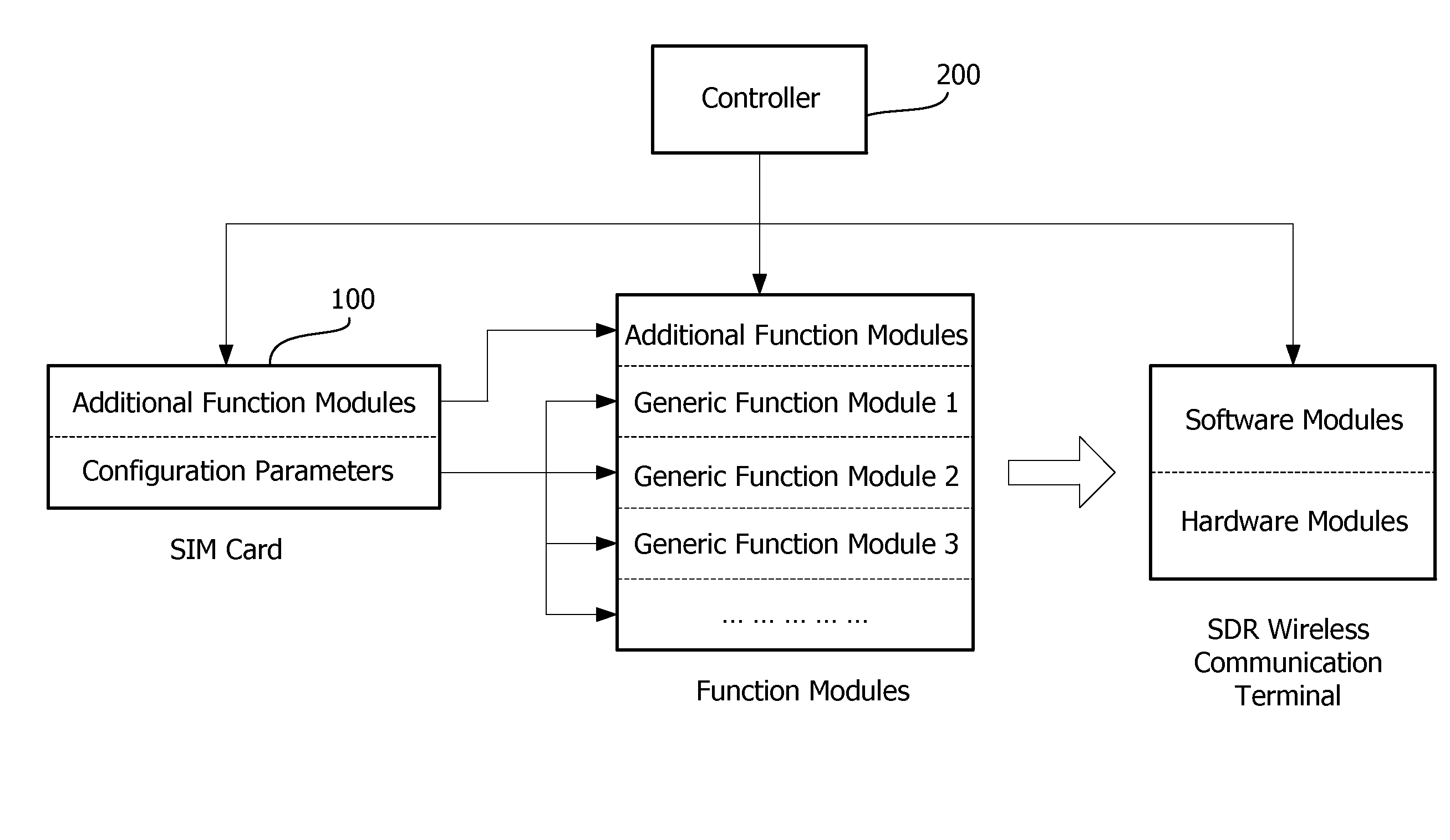
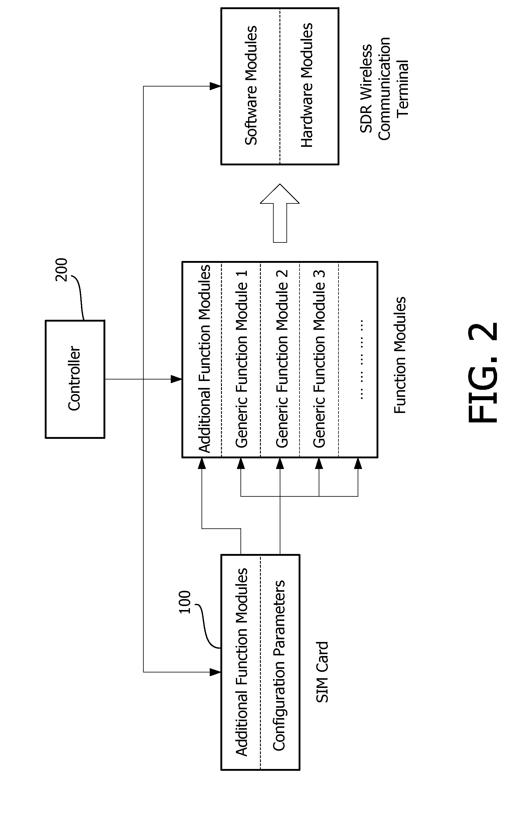
[0016]According to the SDR device and its configuration method in the invention, the SDR device uses generic hardware modules to operate configurable generic software modules so that the SDR device may be configured as desired by using open parameters of the generic software modules as the configuration parameters. The disadvantage of FPGA in the complete software configuration scheme is eliminated and the configuration parameters themselves take up a small data amount, which makes the SDR wireless communication terminals more economic and more flexible for configuration.

Problems solved by technology

Unfortunately, the requirement for complete programmability cannot be met yet under current technical conditions.
It is, therefore, a crucial technical issue in SDR as how to configure the terminal hardware.
Although the above-mentioned complete software configuration scheme has great flexibility in theory, it's very hard to spread to business field in practical applications.
Taking the most common programmable hardware FPGA as an example, it's expensive, as well as bulky and power-consumptive, which limits its use within research or military fields.
Even without consideration of price and cost, it will still be very hard for FPGA to find applications in commercial mobile terminals, because its bulk and power consumption cannot meet the requirements of portability and limited battery capacity for mobile terminals.
From the above analysis of the full software configuration scheme, it can be seen that the complete software configuration scheme currently is only an ideal solution and has no feasibility due to some factors such as cost, power consumption and bulk.

Method used


Image

  • Software defined radio device and configuration method of the same
  • Software defined radio device and configuration method of the same
  • Software defined radio device and configuration method of the same

Examples


Embodiment Construction

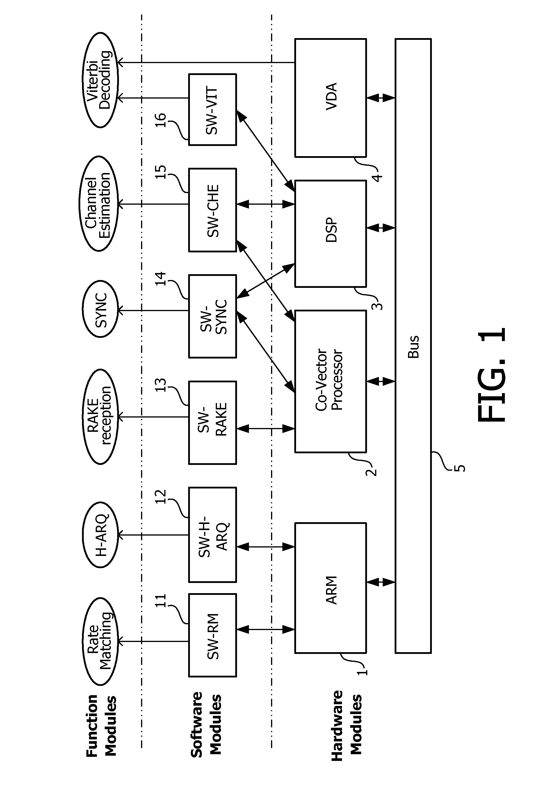
[0024]To make the design of SDR terminals more flexible and efficient, a SDR wireless communication terminal is partitioned into a set of basic generic function modules. The partition is made in accordance with the functional definition of different parts in the SDR terminal, instead of the hardware entities. According to the invention, these generic function modules could be implemented by software running on a general-purpose processor (such as an ARM processor, or a DSP) or re-configurable hardware units (such as a Viterbi decoding co-processor). Such partition realizes a design of a highly flexible architecture for SDR terminal devices. Detailed descriptions will be made below to the invention with reference to the accompanying drawings.

[0025]FIG. 1 is a block diagram illustrating a SDR wireless communication terminal designed with the above partitioning according to an embodiment of the invention. For illustration, FIG. 1 shows only some, rather than all modules in the SDR wire...


PUM


Abstract

The invention discloses a SDR (software defined radio) device and its configuration method. The SDR device has at least one memory for storing a plurality of configurable generic software modules to be configured based on predefined configuration parameters, so that the plurality of configurable generic software modules are adapted to a communication standard corresponding to the configuration parameters; and a plurality of generic hardware modules, for performing instructions in the plurality of configured generic software modules, to accomplish a corresponding function, so as to make the software defined radio device as a communication device complying with the communication standard.

Description

CROSS-REFERENCE TO RELATED APPLICATION(S)[0001]The present application claims priority under 35 U.S.C. §365 to International Patent Application No. PCT / IB2007 / 051407 filed Apr. 19, 2007, entitled “SOFTWARE DEFINED RADIO DEVICE AND CONFIGURATION METHOD OF THE SAME”. International Patent Application No. PCT / IB2007 / 051407 claims priority under 35 U.S.C. §365 and / or 35 U.S.C. §119(a) to Chinese Patent Application No. 200610077447.4 filed Apr. 28, 2006 and which are incorporated herein by reference into the present disclosure as if fully set forth herein.FIELD OF THE INVENTION[0002]The present invention relates to a radio communication technique, and more particularly, to a SDR (software defined radio) device and its configuration method.BACKGROUND OF THE INVENTION[0003]With advances in modern microelectronics and microprocessor technologies, especially emergence of the LSI (Large Scale Integrated Circuit) and programmable logic devices, conventional radio technologies is based mainly on...

Claims


Application Information

Patent Timeline
Patent Type & Authority Patents(United States)
IPC IPC(8): H04B1/40H04B1/403H04B1/00
CPCH04B1/406H04B1/0003
Inventor HU, LIANGLIANGSUN, YANMENG
Owner TELEFON AB LM ERICSSON (PUBL)
Learn More