Method for controlling a scanning microscope

a scanning microscope and control method technology, applied in the field ofatomic force microscopes, can solve the problems of affecting the study of system magnetic and electrical properties, affecting the study of system electrical properties, and the method of working is obviously highly invasive, and achieves the effects of reducing the risk of afm loss, and improving the study

Active Publication Date: 2015-07-28
AUTONOMOUS UNIVERSITY OF MADRID
View PDF11 Cites 0 Cited by
  • Summary
  • Abstract
  • Description
  • Claims
  • Application Information

AI Technical Summary

Benefits of technology

[0010]The present invention involves a new operating method which is simpler and easier to automate and which eliminates the problems described above and is capable of working in all environments in a stable and robust manner. Likewise, the invention makes it possible to obtain data on the magnetic and electrical properties of the systems being studied extremely easily. For this purpose, it proposes a control method of at least two loops for a scanning microscope provided with a micro-cantilever and an actuator adapted to excite the micro-cantilever, in which a first loop has the oscillation amplitude of the micro-cantilever as the controlled variable and the amplitude of the electrical signal introduced into the actuator as the manipulated variable and a second loop uses the amplitude of the previous electrical signal as the controlled variable and the tip-sample distance as the manipulated variable. The amplitude preferably falls within the range of 0.01 nm to 1000 nm. Optionally, a third control loop is provided which has the excitation frequency as the manipulated variable and the movement phase of the lever as the controlled variable. Another fourth optional control loop would have the movement amplitude of the micro-cantilever as the controlled variable and the potential of the continuous component when an electrical potential is applied to it as the manipulated variable.

Problems solved by technology

This method of working is obviously highly invasive due to the direct tip-sample contact, which means that it can only be used on relatively hard, rigid samples in which the forces applied do not constitute a problem.
The main problem associated with the FM method is the possible loss of control of the AFM due to changes in sign in the interaction.
The problem originates in the need to indicate to the feedback system an agreement for altering the manipulated variable.
Due to disturbances (mechanical noise, electrical noise, etc.) it is very common for the domain that does not satisfy the control condition to be entered, thereby destabilizing the microscope.
The interaction of both double-layer structures, as the tip-sample distance diminishes, results in a local electrical force which may complicate interpretation hugely.
On the other hand, the considerable reduction in the attractive range in liquids is not always certain, since on a multitude of occasions attractive interactions appear between the tip and the sample as a result of the capture of unwanted material by the tip, coming from the sample itself or from the liquid medium.

Method used


Image

  • Method for controlling a scanning microscope
  • Method for controlling a scanning microscope
  • Method for controlling a scanning microscope

Examples


Embodiment Construction

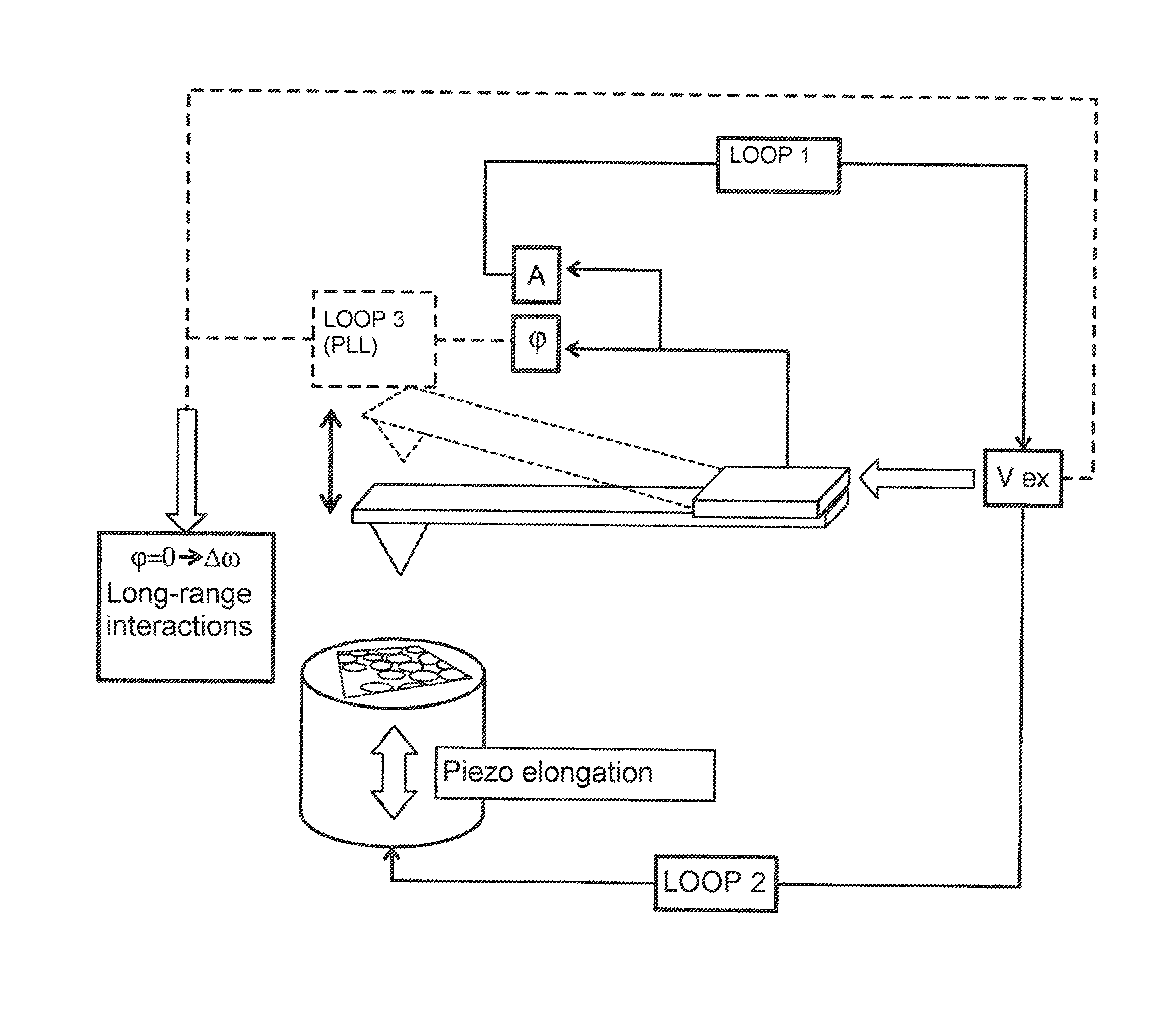
[0018]The control method in the present invention uses two feedback loops. The first loop is responsible for keeping the oscillation amplitude of the micro-cantilever constant at all times (this falls within a range of 0.01 nm to 1000 nm) and for this purpose it uses the amplitude of the electrical signal introduced into the piezoelectric actuator which excites the micro-cantilever as the manipulated variable. The second loop has as the controlled variable the manipulated variable of the above, in other words, the amplitude of the excitation signal. The second loop uses the tip-sample distance as the manipulated variable. In this way, the output of this second loop reproduces the topography of the study sample (FIG. 3).

[0019]In a particular embodiment, a third feedback loop (loop 3) is included which allows the improvement in the image quality when the samples exhibit electrical and / or magnetic interactions to be increased. This feedback system is a phase-locked loop (PPL), which is...


PUM


Abstract

The invention relates to a control method having at least two control loops for a scanning microscope provided with a microlever and an actuator suitable for energizing the microlever, in which a first loop maintains as a controlled variable the oscillation amplitude of the microlever and as a manipulated variable the amplitude of the electric signal supplied to the actuator, and a second loop uses as a controlled variable the amplitude of the aforementioned electric signal and as a manipulated variable the tip-sample distance. Said procedure makes it possible to ignore changes of sign in the tip-sample interaction.

Description

FIELD OF TECHNOLOGY[0001]The invention falls within the field of atomic force microscopes. In particular, it relates to a method for controlling a scanning microscope.BACKGROUND[0002]The atomic force microscope (AFM) is one of the most versatile tools in the exploration and manipulation of micrometric and nanometric-sized systems. Since its invention in the 1980's, this technique has continued improving to the point where it has conquered practically all working environments—from systems that operate under ultra-high vacuum (UHV) conditions to those that are immersed in a liquid medium via, of course, the customary atmospheric conditions in which we ourselves live.[0003]The AFM is based on a micro-lever that acts as a probe. This micro-lever, arranged in a cantilevered manner, in other words with one end fixed and the other one free, has a very sharp tip at its free end. The operation of this tool is based on making the tip of the micro-cantilever interact with the sample or system ...

Claims


Application Information

Patent Timeline
Patent Type & Authority Patents(United States)
IPC IPC(8): G01Q20/04G01Q60/30G01Q60/08G01Q10/04G01Q60/34B82Y35/00
CPCG01Q10/04G01Q60/08G01Q60/30G01Q60/34B82Y35/00
Inventor MARTIN, DAVID MARTINEZRUIZ-CASTELLANOS, MIRIAM JAAFARHERRERO, JULIO GOMEZ
Owner AUTONOMOUS UNIVERSITY OF MADRID
Why Eureka
Try Eureka