
Grommet

a wire harness and grommet technology, which is applied in the direction of electrical/fluid circuit, vehicle components, electrical apparatus, etc., can solve the problems of reducing sealing performance, increasing the burden on workers, and reducing the insertion force during insertion of grommets, so as to prevent excessive deformation and outward deformation, increase sealing performance, and increase the effect of sealing performan

Inactive Publication Date: 2015-08-04
SUMITOMO WIRING SYST LTD
View PDF6 Cites 4 Cited by
  • Summary
  • Abstract
  • Description
  • Claims
  • Application Information

AI Technical Summary

Benefits of technology

The present invention is a grommet designed to prevent excessive deformation during insertion and to increase waterproof performance after mounting. It includes a seal lip that bends appropriately to reduce insertion force and press against the periphery of a through-hole in a proper orientation to increase waterproof performance. The seal lip has a V-shape cross-section that allows it to readily bend and restore its original position after bending. The deformation prevention ribs connect the seal lip to the resin inner holder to regulate bending inward and ensure even bending against the body panel for improved seal performance. Overall, the invention prevents excessive deformation of the seal lip and improves sealing performance during grommet insertion.

Problems solved by technology

In order to increase waterproof performance of a grommet mounted in a through-hole, a large insertion force is required to insert the grommet into the through-hole, thus increasing a burden on a worker.
In particular, with a seal lip that lacks flexibility, the insertion force cannot be reduced during insertion of the grommet.
In the grommet shown in FIGS. 9(A) and 9(B) above as well, when the seal lip 105 does not bend, it is difficult to insert the resin inner 102 into the through-hole H in the body panel P. However, when the seal lip 105 bends outward and deforms excessively, the seal lip 105 cannot be directly pressed against the body panel P, and thus reduces sealing performance.

Method used


Image

  • Grommet
  • Grommet
  • Grommet

Examples


Embodiment Construction

[0033]The particulars shown herein are by way of example and for purposes of illustrative discussion of the embodiments of the present invention only and are presented in the cause of providing what is believed to be the most useful and readily understood description of the principles and conceptual aspects of the present invention. In this regard, no attempt is made to show structural details of the present invention in more detail than is necessary for the fundamental understanding of the present invention, the description taken with the drawings making apparent to those skilled in the art how the forms of the present invention may be embodied in practice.

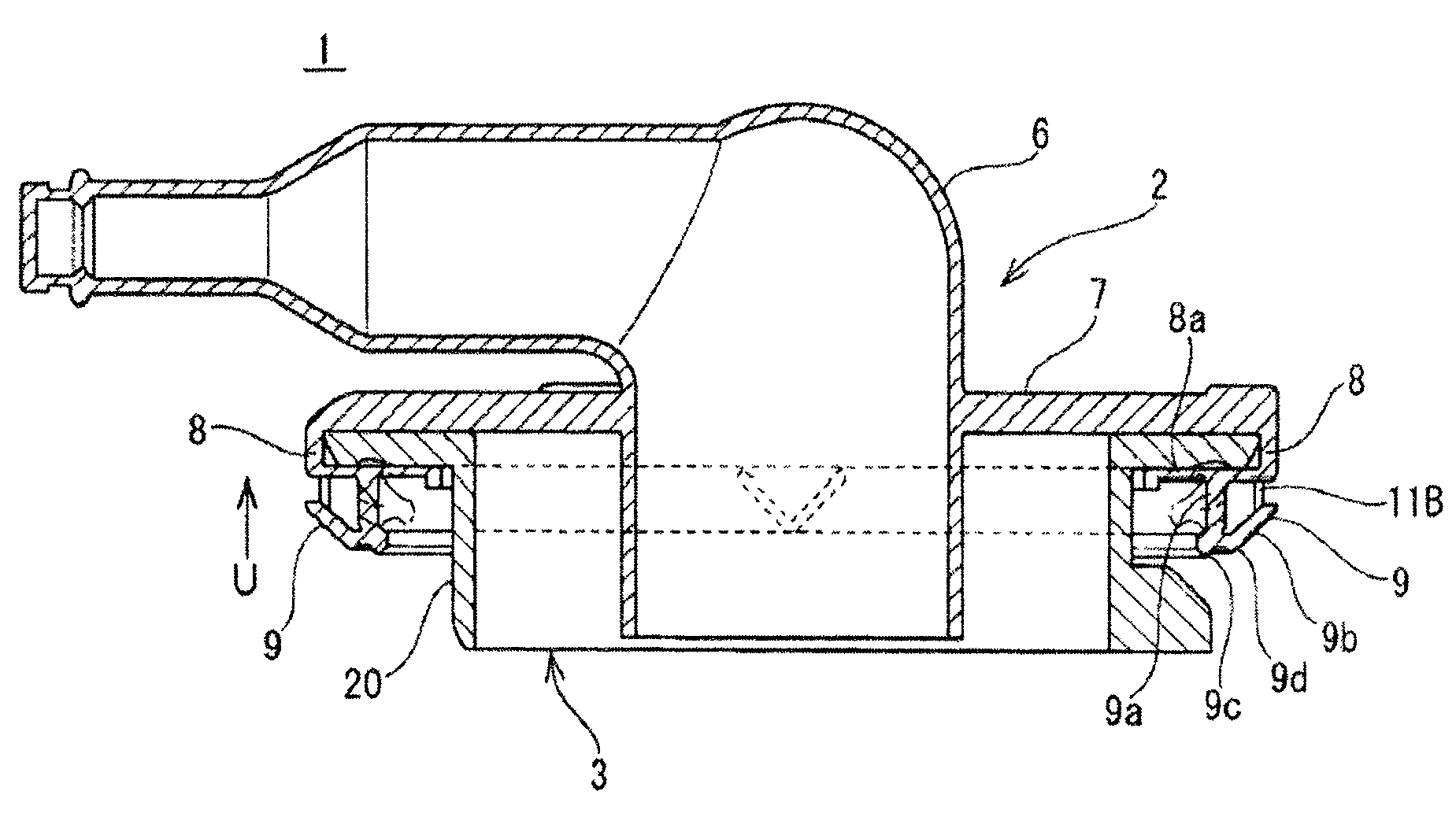
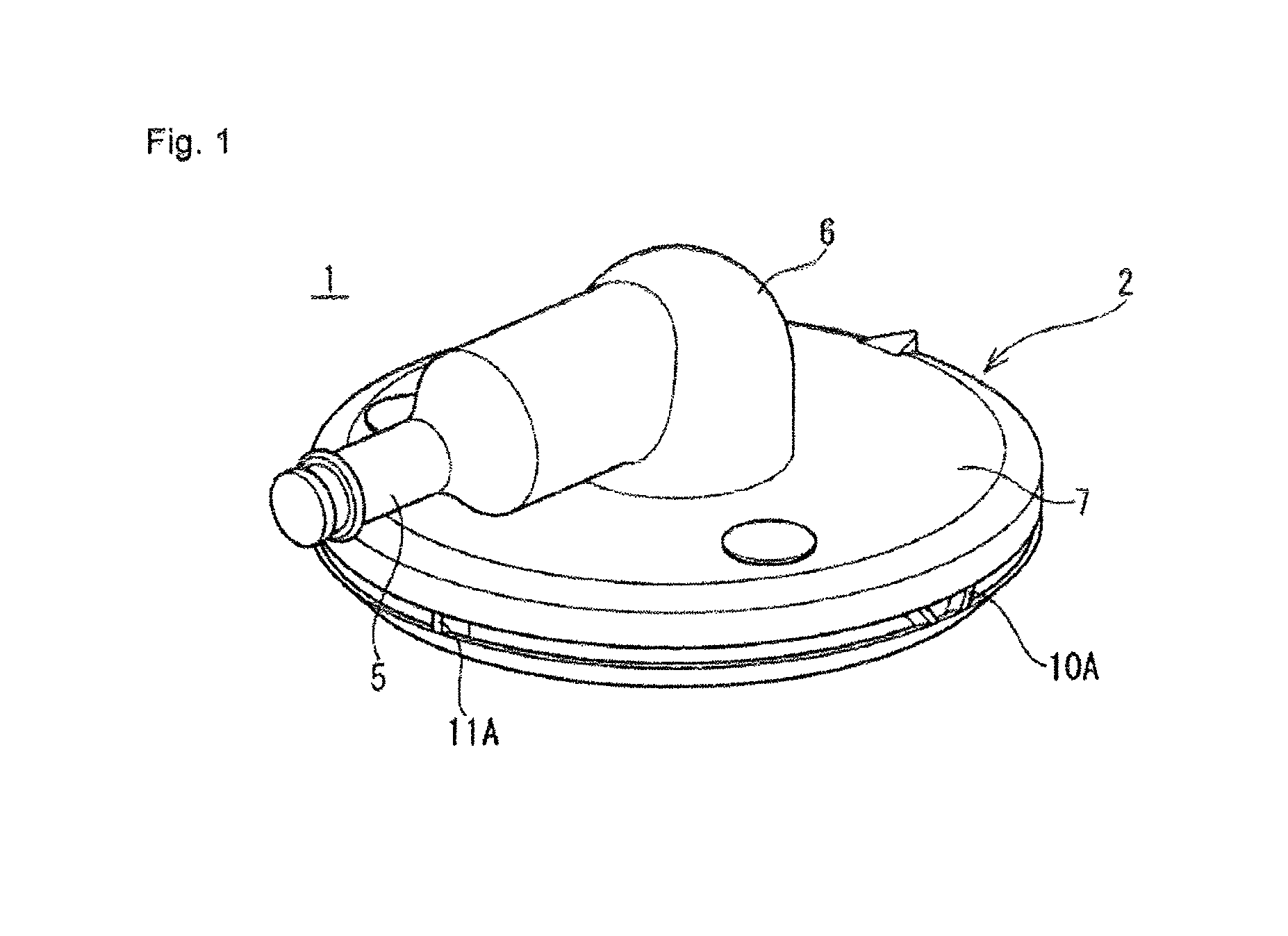
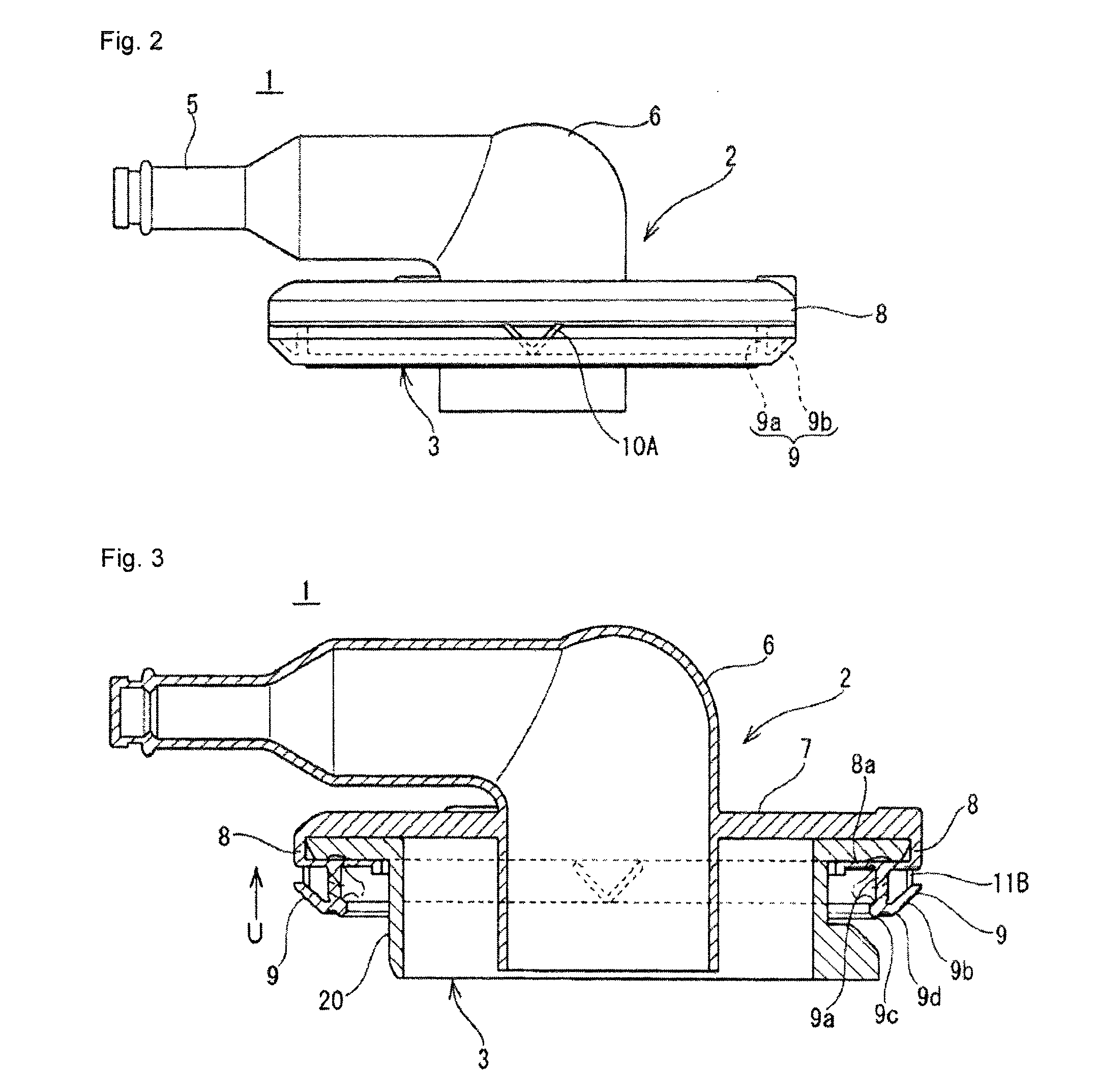
[0034]A grommet according to an embodiment of the present invention is described below with reference to the drawings. FIGS. 1 to 7 illustrate the grommet according to the embodiment of the present invention. A grommet 1 has a flexible grommet main body 2 composed of a rubber or elastomer and a resin inner 3 incorporated into the...


PUM


Abstract

A grommet includes a resin inner assembled to a grommet main body composed of a rubber or elastomer, a seal lip provided in the grommet main body to press against an outer surface of a body panel, and an engagement tab provided in the resin inner to engage with a periphery of a through-hole in the body panel. A base portion of the seal lip projects from a resin inner holder of the grommet main body: An inclined portion projects outward from the base portion. The inclined portion has a seal projection. A plurality of deformation prevention ribs are provided in a circumferential direction with intervals therebetween to connect the front end side of the inclined portion and the resin inner holder.

Description

CROSS-REFERENCE TO RELATED APPLICATIONS[0001]The present application claims priority under 35 U.S.C. §119 of Japanese Application No. 2013-006766, filed on Jan. 17, 2013, the disclosure of which is expressly incorporated by reference herein in its entirety.BACKGROUND OF THE INVENTION[0002]1. Field of the Invention[0003]The present invention relates to a grommet for a wire harness, specifically, a grommet mounted on a wire harness routed in an automobile and mounted in a through-hole of a vehicle body panel, the grommet concurrently enhancing waterproof performance of a seal lip thereof tightly attached to a periphery of the through-hole and reducing force to insert the grommet.[0004]2. Description of Related Art[0005]A grommet for a wire harness of this type is attached to a wire harness inserted through a through-hole of a body panel that partitions inside and outside of a passenger cabin. Then, a seal lip is tightly attached to a periphery of the through-hole to shield the passeng...

Claims


Application Information

Patent Timeline
Patent Type & Authority Patents(United States)
IPC IPC(8): H02G3/22B60R16/02
CPCB60R16/0222
Inventor FUJITA, TETSUYAANDOU, YUUSUKE
Owner SUMITOMO WIRING SYST LTD
Learn More