Discriminative capacitive touch panel

a capacitive touch panel and discrimination technology, applied in the field of capacitive touch panel devices, can solve the problems of reducing the usability of the touch panel, unable to detect multiple simultaneous touch input events, and inability to detect input from non-conductive or insulating objects

Active Publication Date: 2015-08-11
SHARP KK
View PDF20 Cites 29 Cited by
  • Summary
  • Abstract
  • Description
  • Claims
  • Application Information

AI Technical Summary

Benefits of technology

[0009]A capacitive touch panel in accordance with the present invention provides a means of reliably detecting non-conductive input objects as well as conductive input objects and of distinguishing between conductive and non-conductive input objects.
[0012]The capacitive touch panel in accordance with the present invention may be used to advantage in a number of ways, providing convenience or improved experience to the user. For example a capacitive touch panel may be part of a device (such as smart phone, tablet PC or public information device) in which an application (“app”) may execute. A capacitive touch panel provides inputs to the application such as pointing, touching, swiping, gesturing and so on.
[0014]For example, a device comprising the capacitive touch panel in accordance with the present invention may be configured to operate in a different mode depending on what type of input object is used. For example, a drawing application may be configured to draw when a conductive input object is used and to erase when a non-conductive input object is used. In this way the user could conveniently draw in the application using a pencil tip (conductive graphite), then erase in the application using the eraser on the other end of the pencil, and the mode to be detected automatically without any additional action by the user.
[0015]Advantageously, the touch panel in accordance with the present invention therefore provides a means of detecting both conductive and non-conductive types of input object using a capacitive-type touch panel. The usability of the touch panel is therefore improved whilst maintaining the other benefits of the capacitive-type touch panel. Further, the touch panel in accordance with the present invention also provides a means of distinguishing between conductive and non-conductive types of input object and of using this information to improve the usability of a user interface.

Problems solved by technology

Although simple in construction and operation, surface capacitive type touch panels are unable to detect multiple simultaneous touch input events as occurs when, for example, two or more fingers are in contact with the touch panel.
A limitation of the capacitance measurement techniques described above as conventionally applied to touch panels is that they are incapable of detecting input from non-conductive or insulating objects, for example made of wood, plastic or the like.
This disadvantageously reduces the usability of the touch panel since it is restricted to operation using conductive input objects, such as a finger or metallic pen or stylus.
In particular, the user cannot operate a touch panel reliably while wearing normal (non-conductive) gloves or while holding a non-conductive object such as a plastic pen.
The touch panel is not however capable of detecting the location of non-conductive input objects in general.

Method used


Image

  • Discriminative capacitive touch panel
  • Discriminative capacitive touch panel
  • Discriminative capacitive touch panel

Examples


second embodiment

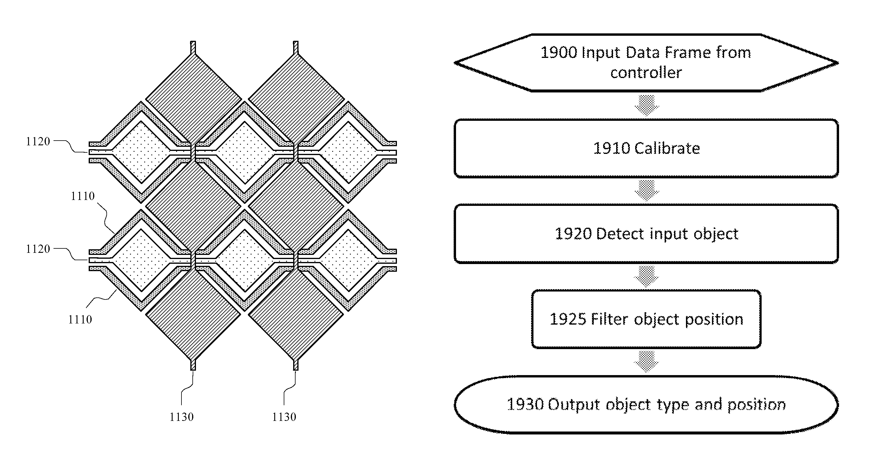
[0225]In accordance with the invention, shown in FIG. 11, the electrode array includes a plurality of drive electrodes and sense electrodes in which the drive electrodes are arranged in pairs such that two drive electrodes are provided at every intersection in the array. Each drive electrode pair includes a first drive electrode, DA 1110, and a second drive electrode, DB 1120. The second drive electrode DB 1120 may have a diamond geometry, while the first drive electrode DA 1110 may be split into two parts that run either side of the second drive electrode DB 1120. The electrode arrangement may be symmetrical around the centre line of the second drive electrode DB 1120. In this way, the second drive electrode DB 1120 is more distant from each sense electrode than the first drive electrode DA 1110. Accordingly, the mutual coupling capacitor between the first drive electrode DA 1110 and the sense electrode is similar to the capacitance CA above and the mutual coupling capacitor betwee...

fourth embodiment

[0229]FIG. 16 shows an electrode arrangement in accordance with the invention. The electrode array of the present embodiment includes a plurality of sense electrode pairs 1600, each pair comprising a first dual-function sense electrode 1610 and a second dual-function sense electrode 1620, and a plurality of drive electrodes 1630, 1650. A first connecting wire 1612 is connected to the first dual-function sense electrode 1610 and a second connecting wire 1622 is connected to the second dual-function sense electrode 1620. The drive electrodes 1630, 1650 and the shapes of the first and second dual function sense electrodes 1610, 1620 may be formed in the transparent conductive layer 420 and the first and second connecting wires 1612, 1622 may be formed in the conductive bridge layer 450. Electrical isolation of the electrodes from the connecting wires is achieved by the insulator layer 460 between the transparent conductive layer 420 and the conductive bridge layer 450. Contact holes 16...

fifth embodiment

[0232]In accordance with the present invention, an electrode array includes sense electrode pairs and drive electrode pairs that are arranged as follows. The sense electrode pairs are divided into odd numbered sense electrode pairs 1700 and even numbered sense electrode pairs 1702. The drive electrode pairs are divided into odd numbered drive electrode pairs 1704 and even numbered drive electrode pairs 1706. The sense electrode pairs are formed by a first and second dual-function sense electrode and the drive electrode pairs are formed by a first and second dual-function drive electrode. As shown in FIG. 17A, the first odd numbered dual-function sense electrode, sense electrode A11710, is adjacent to the first odd numbered drive electrode, drive electrode A11730. The second odd numbered dual-function sense electrode, sense electrode B11720, is adjacent to the first even numbered drive electrode, drive electrode A21735. The first even numbered dual-function sense electrode, sense ele...


PUM


Abstract

A mutual capacitance touch sensor includes a substrate, and an array of electrode elements formed on the substrate. Each electrode element includes at least one of a first electrode group having at least two drive electrodes and at least one sense electrode, or a second electrode group having at least two sense electrodes and at least one drive electrode. The respective electrodes of the first or second group are arranged to form multiple capacitances over different coupling distances. A controller is operatively coupled to the array of electrode elements, the controller configured to assign an input object as a conductive object when measurements of the multiple capacitances decrease as the input object approaches the touch sensor, and assign the input object as non-conductive object when measurements of at least one of the multiple capacitances increase as the input object approaches the touch sensor.

Description

TECHNICAL FIELD AND APPLICATIONS OF THE INVENTION[0001]The present invention relates generally to touch panel devices and, more particularly, to capacitive type touch panels. Such a capacitive type touch panel device may find application in a range of consumer electronic products including, for example, mobile phones, tablet and desktop PCs, electronic book readers and digital signage products.BACKGROUND ART[0002]Touch panels have recently become widely adopted as the input device for high-end portable electronic products such as smart-phones and tablet devices. Although, a number of different technologies can be used to create these touch panels, capacitive systems have proven to be the most popular due to their accuracy, durability and ability to detect touch input events with little or no activation force.[0003]The most basic method of capacitive sensing for touch panels is the surface capacitive method—also known as self-capacitance—for example as disclosed in U.S. Pat. No. 4,29...

Claims


Application Information

Patent Timeline
Patent Type & Authority Patents(United States)
IPC IPC(8): G06F3/045G06F3/0488G06F3/044G09G3/36G06F3/041
CPCG06F3/0416G06F3/044G06F3/0488G09G3/3696G09G2300/0404G09G2300/0426G06F2203/04101G06F3/04166G06F3/04186G06F3/0443G06F3/0446
Inventor BROWN, CHRISTOPHER JAMESKAY, ANDREWSLAMKUL, DAUREN
Owner SHARP KK
Why Eureka
Try Eureka