
3D display devices

a display device and 3d technology, applied in the field of 3d display devices, can solve the problems of narrow viewing angle and devices with a small aperture ratio

Active Publication Date: 2015-08-18
INNOLUX CORP +2
View PDF7 Cites 0 Cited by
  • Summary
  • Abstract
  • Description
  • Claims
  • Application Information

AI Technical Summary

Benefits of technology

This design significantly improves brightness by ensuring all light passes through the liquid crystal molecules perpendicular to their axis, reducing domain boundary effects and achieving peak brightness compared to conventional VA modes.

Problems solved by technology

For the liquid crystal display device, one problem is narrow viewing angle, especially in vertical alignment mode.
The multi-domain, however, causes devices to have a small aperture ratio due to the boundary area between domains.

Method used


Image

  • 3D display devices
  • 3D display devices
  • 3D display devices

Examples


Embodiment Construction

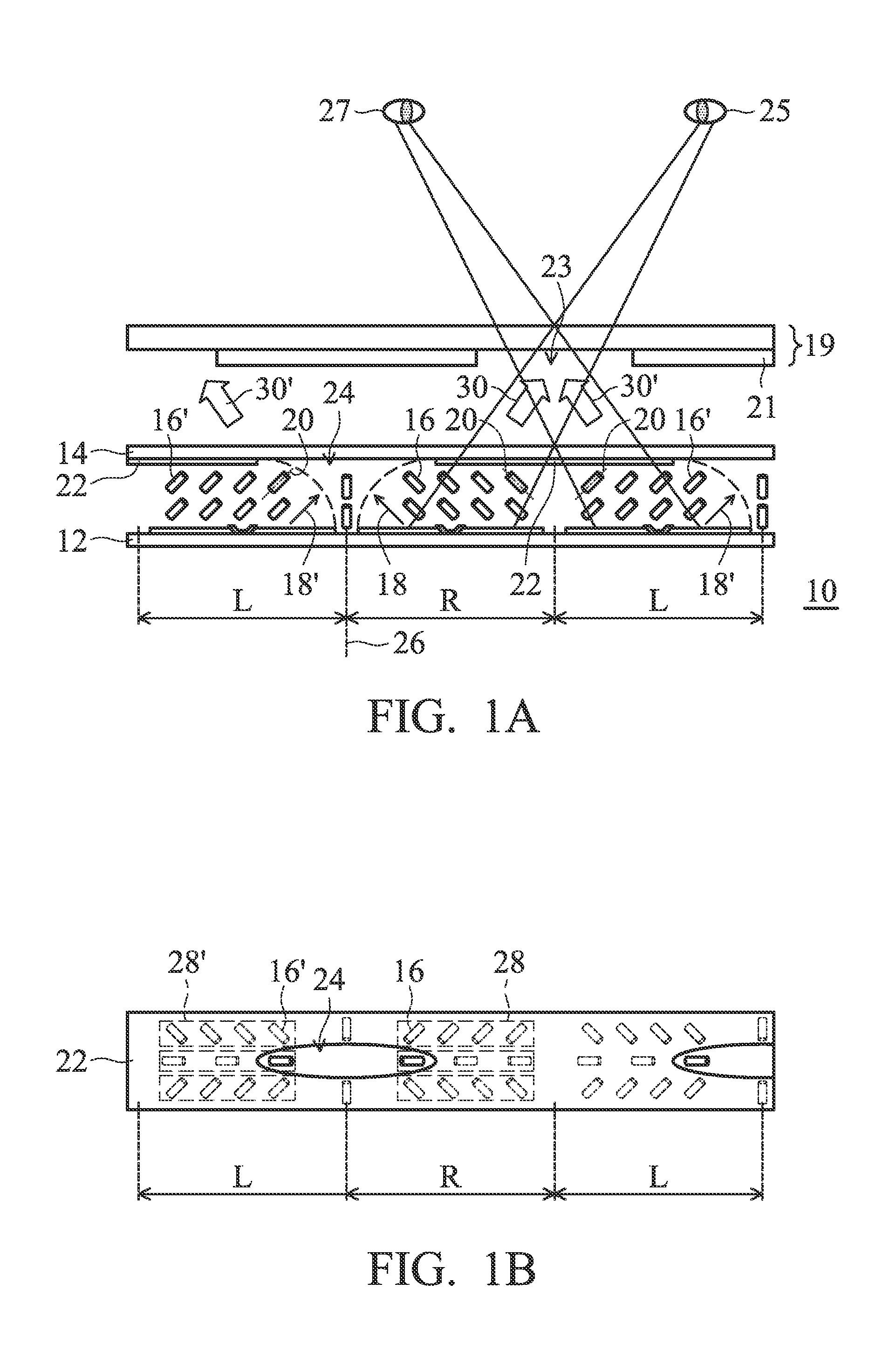
[0023]According to one embodiment of the invention, referring to FIG. 1A, a 3D display device is provided. A 3D display device 10 comprises a first substrate 12 comprising a plurality of right eye pixels R and left eye pixels L in an alternate arrangement, a second substrate 14 opposite to the first substrate 12, a first optical modulating unit 16 with a first inclined direction 18 located in the right eye pixels R between the first substrate 12 and the second substrate 14, a second optical modulating unit 16′ with a second inclined direction 18′ located in the left eye pixels L between the first substrate 12 and the second substrate 14, and a light transparent element 19 disposed between the second substrate 14 and an observer. The first inclined direction 18 is distinct from the second inclined direction 18′.

[0024]The first substrate 12 may be a thin film transistor (TFT) array substrate. The second substrate 14 may be a color filter (CF) array substrate. In this embodiment, the l...


PUM

PropertyMeasurementUnit
light transparentaaaaaaaaaa
brightnessaaaaaaaaaa
sizeaaaaaaaaaa

Abstract

In an embodiment of the invention, a 3D display device is provided. The 3D display device includes: a first substrate including a plurality of right eye pixels and left eye pixels in an alternate arrangement; a second substrate opposite to the first substrate; a first optical modulating unit with a first inclined direction located in the right eye pixels between the first substrate and the second substrate; a second optical modulating unit with a second inclined direction located in the left eye pixels between the first substrate and the second substrate, wherein the first inclined direction is distinct from the second inclined direction; and a light transparent element disposed on the second substrate.

Description

BACKGROUND OF THE INVENTION[0001]1. Field of the Invention[0002]The invention relates to a 3D display device, and in particular to a 3D display device capable of improving brightness.[0003]2. Description of the Related Art[0004]Liquid crystal display devices are used for many kinds of electronic devices such as a mobile telephone, a television receiver, or the like, and much research has been done for further improving the quality.[0005]While the advantages of a liquid crystal display device are its small size, light weight, and low power consumption compared to a CRT (cathode-ray tube). For the liquid crystal display device, one problem is narrow viewing angle, especially in vertical alignment mode. In-plane switching mode liquid crystal alignment has better viewing angle performance. In recent years, much research has been done on multi domain methods. That is, an alignment division method to improve viewing angle characteristics. For example, an MVA (multi-domain vertical alignme...

Claims


Application Information

Patent Timeline
Patent Type & Authority Patents(United States)
IPC IPC(8): G02F1/1335G02B27/22G02F1/1343G02F1/167G02F1/1337G02B30/27G02B30/28G02B30/30G02B30/31G02F1/1676
CPCG02B27/225G02F1/133753G02F1/134363G02F2001/1676G02F1/1676G02B30/31G02B30/30G02B30/28G02B30/27G02F1/134309
Inventor INADA, TOSHIYA
Owner INNOLUX CORP
Features
  • Generate Ideas
  • Intellectual Property
  • Life Sciences
  • Materials
  • Tech Scout
  • Unparalleled Data Quality
  • Higher Quality Content
  • 60% Fewer Hallucinations
Learn More