Supercharge Your Innovation With Domain-Expert AI Agents!

Fuel cell separator material, fuel cell separator using same, and fuel cell stack

a technology of separator and separator material, which is applied in the direction of cell components, cell component details, electrochemical generators, etc., can solve the problems of high material cost and processing cost, undetected corrosion and elution at high temperature under oxidizing atmospher

Active Publication Date: 2015-09-01
JX NIPPON MINING & METALS CORP
View PDF35 Cites 1 Cited by
  • Summary
  • Abstract
  • Description
  • Claims
  • Application Information

AI Technical Summary

Benefits of technology

[0016]Through diligent studies, the present inventors found that an intermediate layer containing Ti and O and the predetermined metal is formed on a surface of a Ti base, and an alloy layer or an Au single layer is formed on the intermediate layer, whereby an Au (alloy) layer can be formed on Ti strongly and uniformly, and corrosion resistance and durability required for a fuel cell separator can be obtained.
[0019]Preferably, a metal layer comprising the first component having a thickness of 5 nm or less is formed or is not formed between the alloy layer and the intermediate layer. The corrosion resistance improves when the thickness of the metal layer becomes thin.
[0020]Preferably, the concentration of the Au in the alloy layer is increased from the bottom layer to the upper layer. When an Au single layer is formed on the surface of the alloy layer, good corrosion resistance, electrical conductivity and durability is shown even the separator is used under the conditions of a fuel cell.
[0026]According to the present invention, since an intermediate layer containing Ti, O, and the predetermined metal is formed on the surface of the Ti base, and the alloy layer or the Au single layer is formed on the intermediate layer, the Au layer or the layer containing Au can be formed strongly and uniformly on Ti, and corrosion resistance, electrical conductivity and durability required for a fuel cell separator can be obtained.

Problems solved by technology

However, it is undesirable in that material costs and processing costs are high.
On the other hand, when a metal plate is used in place of the carbon plate, it might undesirably be corroded and eluted at high temperature under oxidizing atmosphere.

Method used


Image

  • Fuel cell separator material, fuel cell separator using same, and fuel cell stack
  • Fuel cell separator material, fuel cell separator using same, and fuel cell stack
  • Fuel cell separator material, fuel cell separator using same, and fuel cell stack

Examples


examples

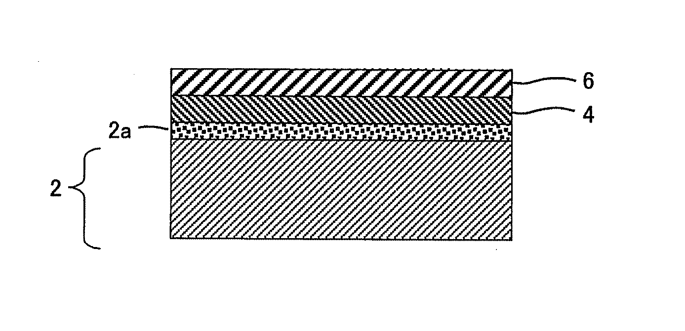
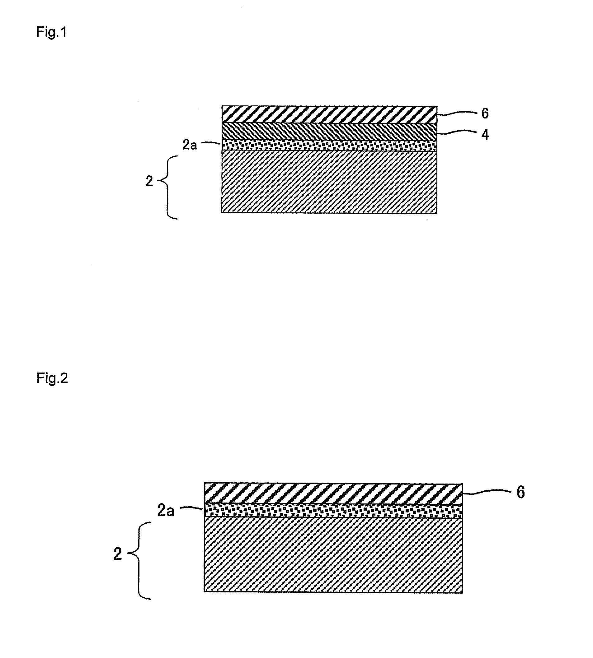
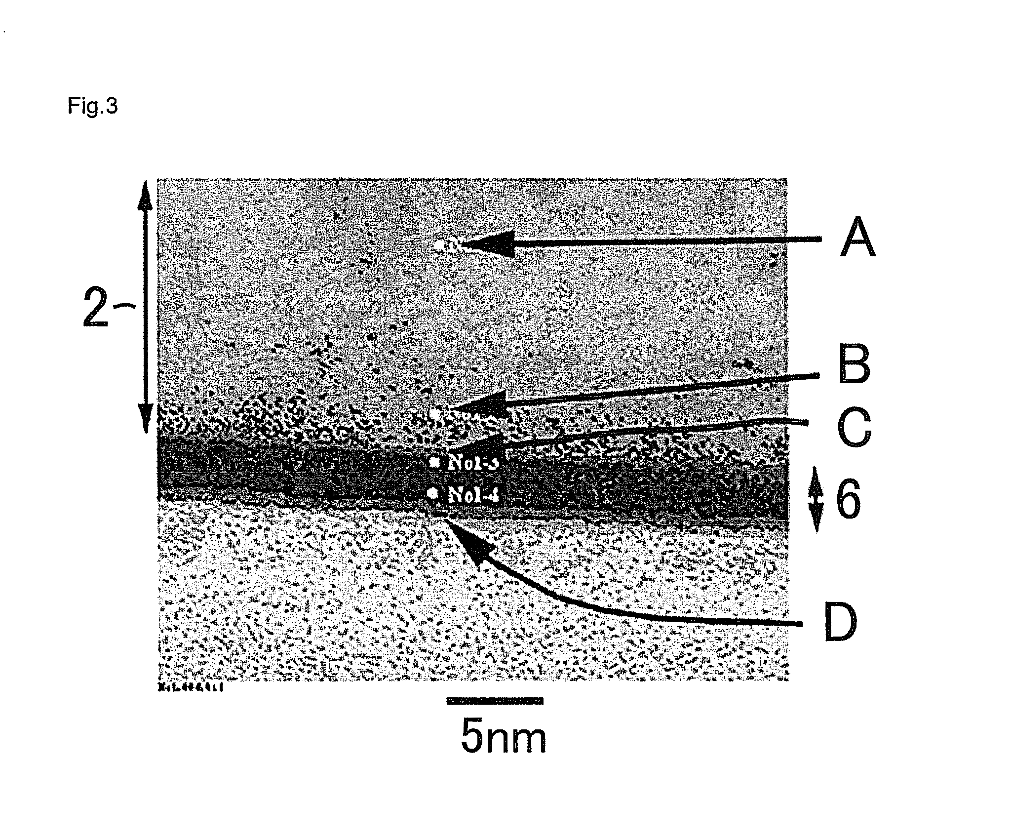
[0138]A commercially pure titanium sheet (JIS 1st class) having a thickness of 100 μm was used as the Ti base and was pre-treated with FIB (focused ion beam system). The Ti base was observed with energy-dispersive X-ray spectroscopy (EDX) of FE-TEM (field-emission transmission electron microscopy). It was identified that a titanium oxide layer having a thickness of about 6 nm was already formed on the surface of the Ti base.

[0139]In some examples, the Ti base (Ti coated base) was used by coating a Ti coating with a predetermined thickness as shown in Tables 1 and 2 on a commercially pure stainless steel sheet (SUS316L) having a thickness of 100 μm. Ti was coated with vacuum deposition using an electron beam vapor deposition system (manufactured by ULVAC-PHI, Inc., MB05-1006).

[0140]Then, a Cr or Mo layer (metal layer) was formed on the surface of the titanium oxide layer of the Ti base using a sputtering method to have the predetermined target thickness. A Cr or Mo target was used. T...


PUM

PropertyMeasurementUnit
thicknessaaaaaaaaaa
thicknessaaaaaaaaaa
thicknessaaaaaaaaaa

Abstract

A fuel cell separator material, comprising an alloy layer 6 containing Au and a first component containing Al, Cr, Fe, Co, Ni, Cu, Mo, Sn or Bi, or an Au single layer 8 formed on a Ti base 2; an intermediate layer 2a containing Ti, O, the first component, and less than 20 mass % of Au arranged between the alloy layer or the Au single layer and the Ti base; wherein the alloy layer or the Au single layer has a region having a thickness of 1 nm or more from the uppermost to the lower layer and containing 50 mass % or more of Au, or a region having a thickness of 3 nm or more from the uppermost to the lower layer and containing Au in the range from 10-50 mass %, or the thickness of the Au single layer is 1 nm or more.

Description

FIELD OF THE INVENTION[0001]The present invention relates to a fuel cell separator material on which Au or an Au alloy (a layer containing Au) is formed, a fuel cell separator using the same and a fuel cell stack.DESCRIPTION OF THE RELATED ART[0002]Traditionally, as a polymer electrolyte fuel cell separator, a carbon plate on which gas flow paths are formed has been used. However, it is undesirable in that material costs and processing costs are high. On the other hand, when a metal plate is used in place of the carbon plate, it might undesirably be corroded and eluted at high temperature under oxidizing atmosphere. To avoid this, there is a known technology that an alloy of Au and a noble metal selected from Au, Ru, Rh, Pd, Os, Ir, Pt or the like is sputtered on a Ti plate to form an electrical conductive portion (see Patent Literature 1). In addition, Patent Literature 1 describes that the oxide of the aforementioned noble metal is formed on a Ti surface.[0003]Meanwhile, it is kno...

Claims


Application Information

Patent Timeline
Patent Type & Authority Patents(United States)
IPC IPC(8): H01M2/16H01M8/02H01M8/24H01M8/10
CPCH01M8/0228H01M8/0206H01M8/0215H01M8/1011H01M2008/1095Y02E60/50Y02E60/523C23C30/00H01M8/02H01M8/10
Inventor SHIBUYA, YOSHITAKA
Owner JX NIPPON MINING & METALS CORP
Features
  • R&D
  • Intellectual Property
  • Life Sciences
  • Materials
  • Tech Scout
  • Unparalleled Data Quality
  • Higher Quality Content
  • 60% Fewer Hallucinations
Learn More