Supercharge Your Innovation With Domain-Expert AI Agents!

Fuel cell separator material, fuel cell separator using same, and fuel cell stack

a technology of separator and separator material, which is applied in the direction of cell components, cell component details, electrochemical generators, etc., can solve the problems of high material cost and processing cost, undetected corrosion and elution at high temperature under oxidizing atmospher

Active Publication Date: 2011-10-27
JX NIPPON MINING& METALS CORP
View PDF4 Cites 5 Cited by
  • Summary
  • Abstract
  • Description
  • Claims
  • Application Information

AI Technical Summary

Benefits of technology

[0016]Through diligent studies, the present inventors found that an intermediate layer containing Ti and O and the predetermined metal is formed on a surface of a Ti base, and an alloy layer or an Au single layer is formed on the intermediate layer, whereby an Au (alloy) layer can be formed on Ti strongly and uniformly, and corrosion resistance and durability required for a fuel cell separator can be obtained.
[0019]Preferably, a metal layer comprising the first component having a thickness of 5 nm or less is formed or is not formed between the alloy layer and the intermediate layer. The corrosion resistance improves when the thickness of the metal layer becomes thin.
[0020]Preferably, the concentration of the Au in the alloy layer is increased from the bottom layer to the upper layer. When an Au single layer is formed on the surface of the alloy layer, good corrosion resistance, electrical conductivity and durability is shown even the separator is used under the conditions of a fuel cell.
[0026]According to the present invention, since an intermediate layer containing Ti, O, and the predetermined metal is formed on the surface of the Ti base, and the alloy layer or the Au single layer is formed on the intermediate layer, the Au layer or the layer containing Au can be formed strongly and uniformly on Ti, and corrosion resistance, electrical conductivity and durability required for a fuel cell separator can be obtained.

Problems solved by technology

However, it is undesirable in that material costs and processing costs are high.
On the other hand, when a metal plate is used in place of the carbon plate, it might undesirably be corroded and eluted at high temperature under oxidizing atmosphere.

Method used


Image

  • Fuel cell separator material, fuel cell separator using same, and fuel cell stack
  • Fuel cell separator material, fuel cell separator using same, and fuel cell stack
  • Fuel cell separator material, fuel cell separator using same, and fuel cell stack

Examples


first embodiment

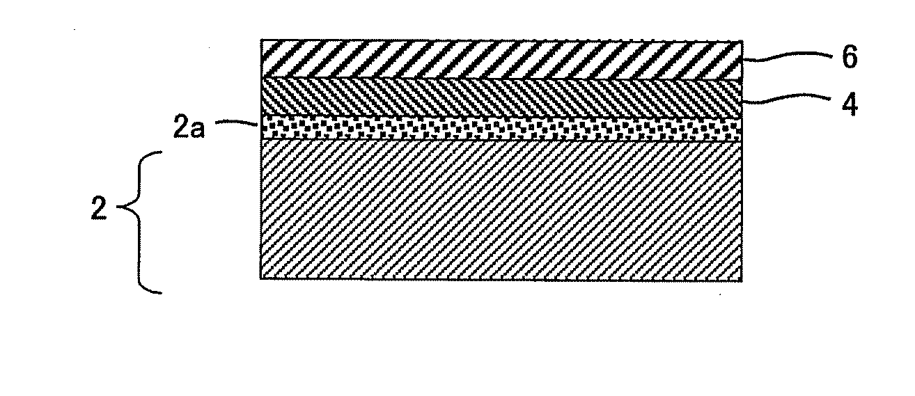
[0041]The fuel cell separator material according to a first embodiment of the present invention will be described below. As shown in FIG. 1, the fuel cell separator material according to the first embodiment comprises a metal layer 4 formed on a surface of a Ti base 2 via an intermediate layer 2a, and an alloy layer 6 formed on a surface of the metal layer 4. The metal layer 4 mainly comprises the above-mentioned metal (preferably the same as the first component of the intermediate layer).

[0042]The fuel cell separator material requires corrosion resistance and electrical conductivity, and the base requires corrosion resistance. So, a titanium material having good corrosion resistance is used as the base.

[0043]The Ti base may be solid titanium, or may be a material other than Ti having a Ti coating thereon with a thickness of 10 nm or more. Examples of the material other than Ti include stainless steel and aluminum. When Ti is coated on the surface of the material, lower corrosion re...

second embodiment

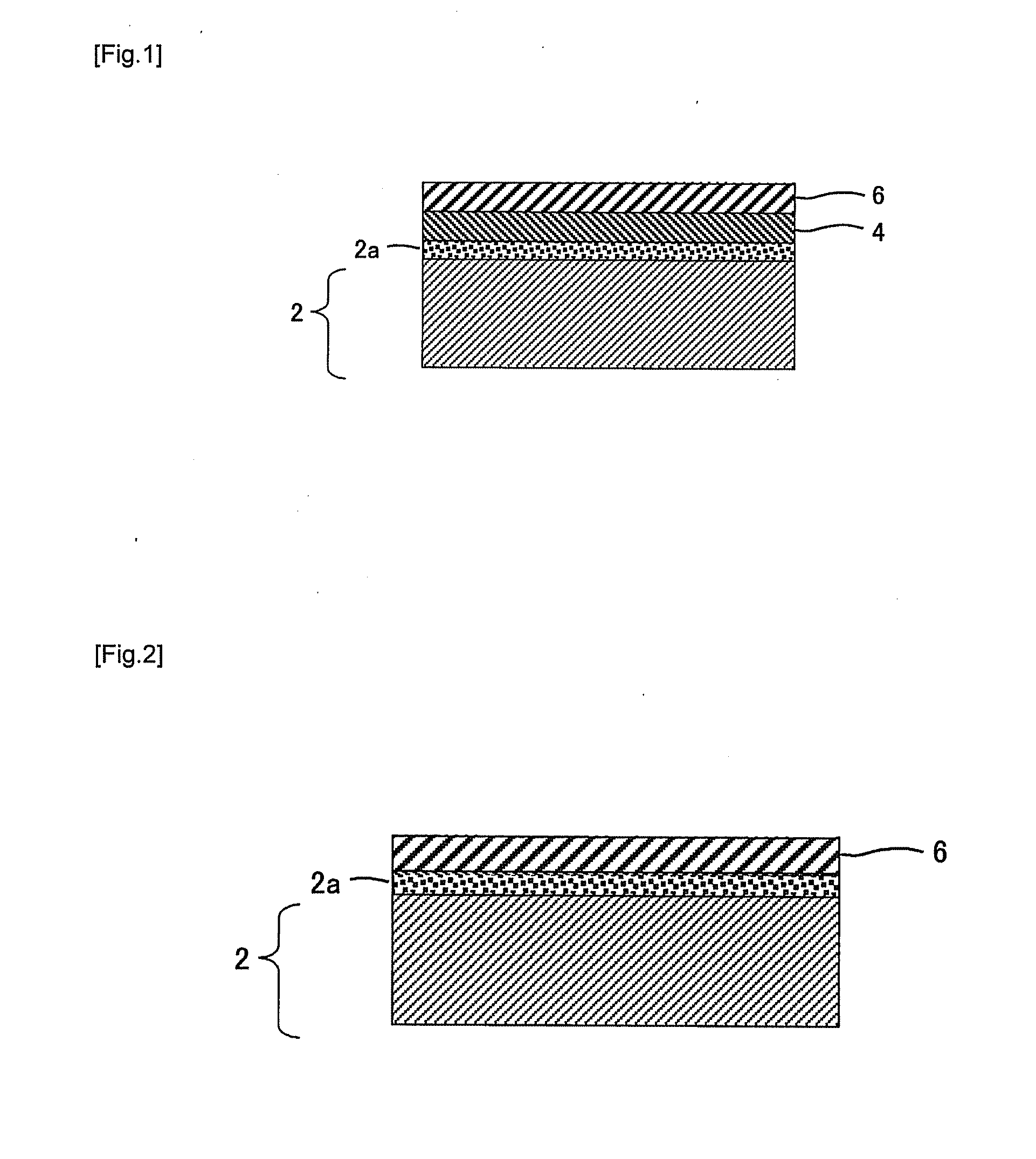
[0083]The fuel cell separator material according to a second embodiment of the present invention will be described below. As shown in FIG. 2, the fuel cell separator material according to the second embodiment comprises an intermediate layer 2a formed on a surface of a Ti base 2, and an alloy layer 6 formed on the intermediate layer 2a.

[0084]Since the Ti base 2 and the alloy layer 6 are the same as the first embodiment, a description is omitted. The fuel cell separator material according to the second embodiment is different from the first embodiment in that no metal layer 4 is formed, and has excellent corrosion resistance as compared with the first embodiment.

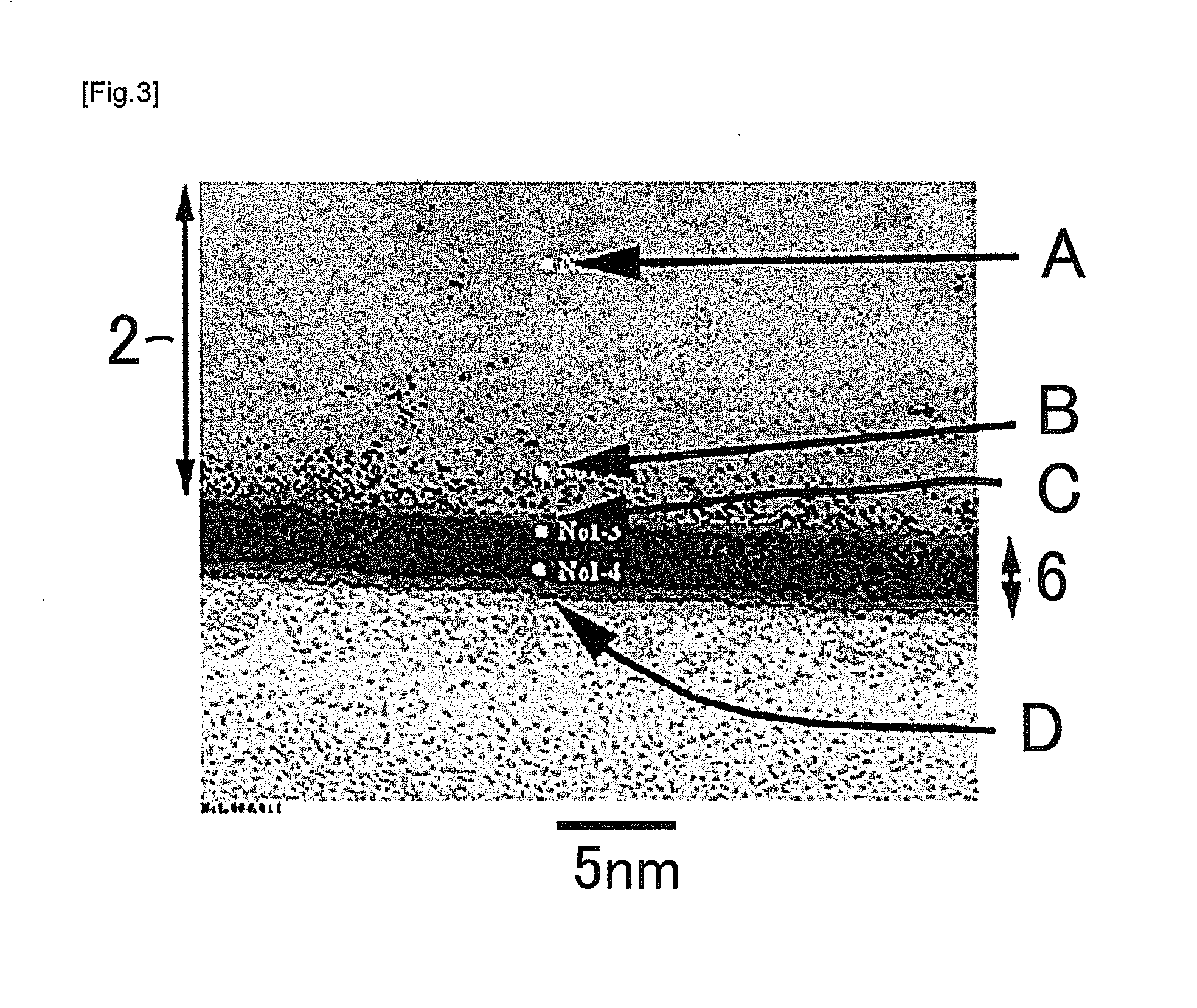
[0085]Also in the second embodiment, the concentration of O in the depth region of the alloy layer 6 having the Au concentration of 10% is preferably 30% by mass or less. The depth region of the alloy layer 6 having the Au concentration of 10% is a boundary between the intermediate layer 2a and the alloy layer 6. If the regi...

third embodiment

[0089]The fuel cell separator material according to a third embodiment of the present invention will be described below. As shown in FIG. 5, the fuel cell separator material according to the third embodiment comprises an alloy layer 6 formed on a surface of a Ti base 2 via an intermediate layer 2a, and an Au single layer 8 is formed on the surface of the alloy layer 6. Since the Ti base 2 and the alloy layer 6 are the same as the first embodiment, a description is omitted.

[0090]The Au single layer 8 can be formed appropriately by changing the sputter conditions (sputter time, output and the like).

[0091]Alternatively, the layer structures of the first and third embodiments may be combined to form a layer structure having the metal layer 4, the alloy layer 6 and the Au single layer 8 in order via the intermediate layer 2a on the surface of the Ti base 2.

[0092]According to the fuel cell separator material embodiments of the present invention, the Au (alloy) layer can be formed on the T...


PUM

PropertyMeasurementUnit
Percent by massaaaaaaaaaa

Abstract

A fuel cell separator material, comprising an alloy layer 6 containing Au and a first component containing Al, Cr, Fe, Co, Ni, Cu, Mo, Sn or Bi, or an Au single layer 8 formed on a Ti base 2; an intermediate layer 2a containing Ti, O, the first component, and less than 20 mass % of Au arranged between the alloy layer or the Au single layer and the Ti base; wherein the alloy layer or the Au single layer has a region having a thickness of 1 nm or more from the uppermost to the lower layer and containing 50 mass % or more of Au, or a region having a thickness of 3 nm or more from the uppermost to the lower layer and containing Au in the range from 10-50 mass %, or the thickness of the Au single layer is 1 nm or more.

Description

FIELD OF THE INVENTION[0001]The present invention relates to a fuel cell separator material on which Au or an Au alloy (a layer containing Au) is formed, a fuel cell separator using the same and a fuel cell stack.DESCRIPTION OF THE RELATED ART[0002]Traditionally, as a polymer electrolyte fuel cell separator, a carbon plate on which gas flow paths are formed has been used. However, it is undesirable in that material costs and processing costs are high. On the other hand, when a metal plate is used in place of the carbon plate, it might undesirably be corroded and eluted at high temperature under oxidizing atmosphere. To avoid this, there is a known technology that an alloy of Au and a noble metal selected from Au, Ru, Rh, Pd, Os, Ir, Pt or the like is sputtered on a Ti plate to form an electrical conductive portion (see Patent Literature 1). In addition, Patent Literature 1 describes that the oxide of the aforementioned noble metal is formed on a Ti surface.[0003]Meanwhile, it is kno...

Claims


Application Information

Patent Timeline
IPC IPC(8): H01M2/16H01M8/24H01M8/04
CPCH01M8/0206H01M8/0215H01M8/0228Y02E60/50H01M2008/1095Y02E60/523H01M8/1011C23C30/00H01M8/02H01M8/10
Inventor SHIBUYA, YOSHITAKA
Owner JX NIPPON MINING& METALS CORP
Features
  • R&D
  • Intellectual Property
  • Life Sciences
  • Materials
  • Tech Scout
  • Unparalleled Data Quality
  • Higher Quality Content
  • 60% Fewer Hallucinations
Learn More