
LED lamp

a technology of led lamps and led lamps, applied in the field of electric lighting devices, can solve the problems of inefficiency of light dispersion, relatively high power consumption of lighting apparatuses, and inefficiency of lighting

Active Publication Date: 2015-09-08
LIN WAN JIONG +2
View PDF3 Cites 3 Cited by
  • Summary
  • Abstract
  • Description
  • Claims
  • Application Information

AI Technical Summary

Benefits of technology

The patent text describes LED lighting apparatuses that replacing traditional lighting methods such as halogen, incandescent, and fluorescence. However, these LED lighting apparatuses have limitations in achieving narrow beam angles and providing optimal lighting. Additionally, they experience glare and inefficient heat distribution, which hinders the use of high-powered LEDs. The technical effects of the patent text are to address these limitations and provide an improved LED lighting apparatus that can achieve narrow beam angles, reduce glare, and efficiently distribute heat.

Problems solved by technology

However, such lighting apparatus presents a number of drawbacks.
For example, the popular halogen apparatus presents the following drawbacks, such as relatively high power consumption, inefficiency of light dispersion due to the placement of its metal shield in the line sight of the halogen bulb, and its limited effectiveness in preventing glare from the halogen bulb.
These configurations are unable to achieve narrow beam angles, and result in considerable glare since observers are not shielded from the LED light source.
Further, these configurations inefficiently distribute heat; thereby, making the use of high-powered LEDs in these configurations practically prohibitive.

Method used


Image

  • LED lamp
  • LED lamp
  • LED lamp

Examples


Embodiment Construction

[0020]The disclosure is illustrated by way of example and not by way of limitation in the figures of the accompanying drawings. It should be noted that references to “an” or “one” embodiment in this disclosure are not necessarily to the same embodiment, and such references mean at least one.

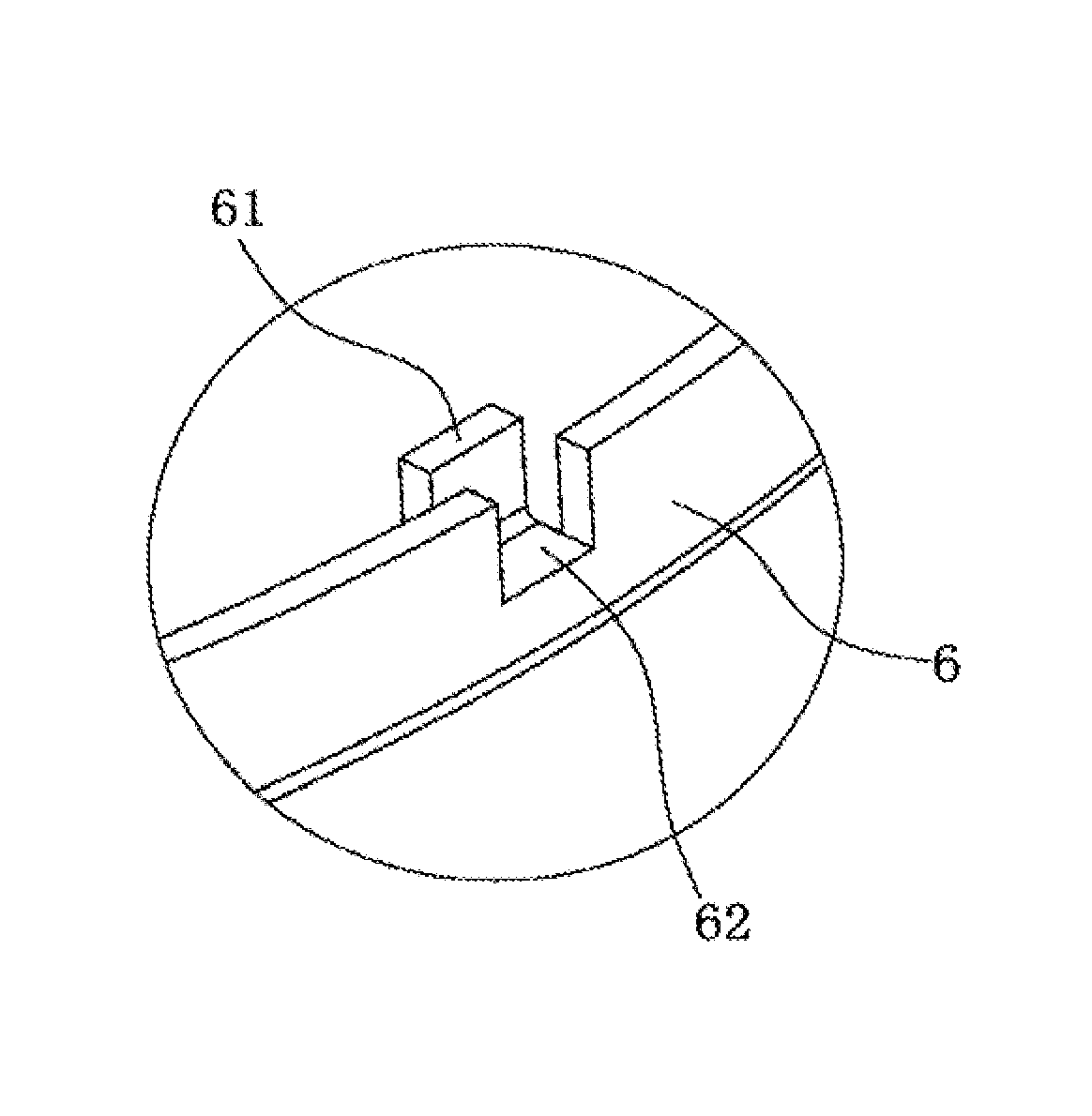
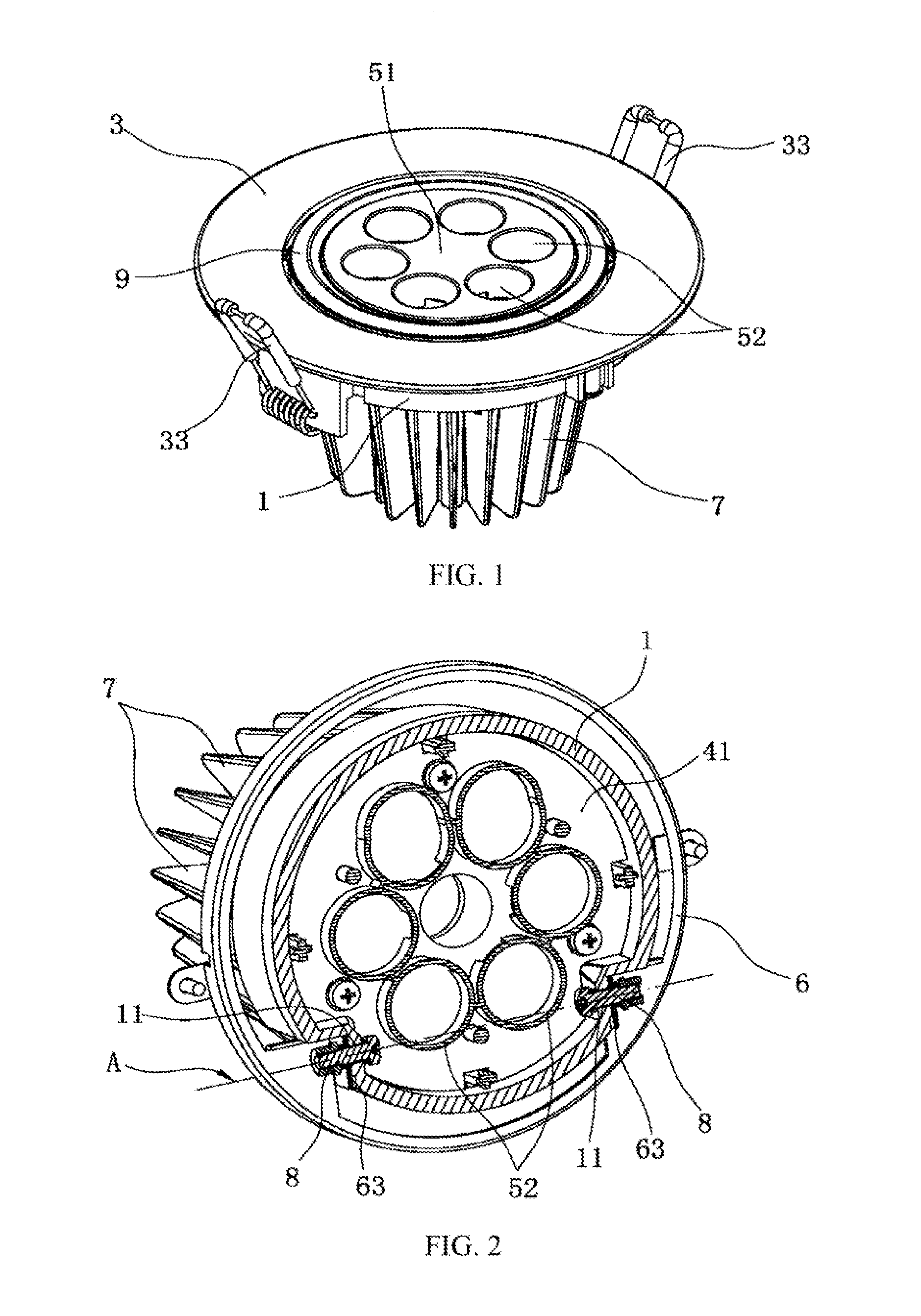
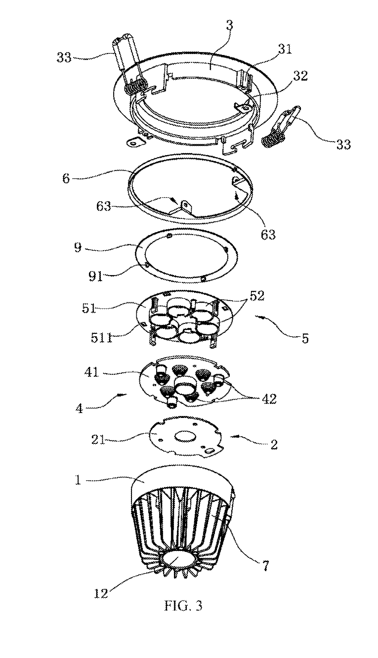
[0021]Referring to FIGS. 1-12, a LED lamp according to an embodiment is shown. The LED lamp includes a house 1, a light module 2 mounted in the house 1, lens module 4 received in the house 1 along an optical axis of the light module 2, a shade module 5 arranged in the lens module 4, a light frame 3 mounted in front of the house 1, and a ring 6 surrounding the house 1.

[0022]Referring to FIG. 11 together with FIG. 1, the house 1 has a cup-shaped structure and includes a number of heat sinks 7 around outer surface thereof, a first through hole 12 opened along a circumference axis thereof, a place for mounting the light module 2, and two first pin holes 11 being respectively opened in two side walls ...


PUM


Abstract

A LED lamp includes a number of lenses each of which includes a light emitting surface and a plurality of shades mounted on the light emitting surface. Each of the shades includes a hole whose sectional area in radial direction is equal to that of the light emitting surface. An axial height of the hole follows the formulaHφ=ϕ⁢maxtan⁢⁢θmax,wherein Hφ is the axial height of the hole, φmax is a diameter value of the light emitting surface, and θmax is an output angle of the lens. Accordingly, a work area of the anti-glare LED lamp can be extend the most thereof since the shades block the stray light of a glare area of the LED lamp and strictly separates the work area from the glare area, and no stray light shot into eye in any areas. Therefore, the anti-glare LED lamp can achieve light distribution as designed without glare under cooperation of the lenses and the shades.

Description

CROSS REFERENCE TO RELATED APPLICATION[0001]This application is a national phase application of and claims the benefits of PCT Application No. PCT / CN / 2010 / 002138, filed on Dec. 23, 2010.BACKGROUND[0002]1. Technical Field[0003]The disclosure relates to electrical lighting devices, and more particularly to an LED lamp using at least one single-chip or multi-chip light-emitting-diode (“LED”), and a shade module which minimizing glare.[0004]2. Description of the Related Art[0005]For years, people have used traditional incandescent or fluorescence lighting apparatus in order to address their interior lighting concerns. However, such lighting apparatus presents a number of drawbacks. For example, the popular halogen apparatus presents the following drawbacks, such as relatively high power consumption, inefficiency of light dispersion due to the placement of its metal shield in the line sight of the halogen bulb, and its limited effectiveness in preventing glare from the halogen bulb.[0006...

Claims


Application Information

Patent Timeline
Patent Type & Authority Patents(United States)
IPC IPC(8): F21V3/00F21V11/06F21V13/14F21V5/00F21V29/77F21S8/02F21V1/00F21V29/00F21V5/04F21V7/00F21Y101/02
CPCF21V1/00F21S8/02F21V5/00F21V11/06F21V13/14F21V29/004F21V29/773F21V5/04F21V7/0091F21Y2101/02F21Y2115/10F21K9/60
Inventor ZHANG, FA-WEIZHU, TAO-LINZHENG, ZHAO-YONGLIN, WAN-JIONG
Owner LIN WAN JIONG
Learn More