Filter element for an air inlet system

a filter element and air inlet technology, applied in the field of filter element for air inlet system, can solve the problems of inhomogeneous speed distribution, local speed peak, damage to the filter medium, etc., and achieve the effects of preventing or greatly reducing the acoustic impairment of the vibrating inflow protection element, and improving the performance of the air inlet system

Active Publication Date: 2015-09-15
MANN HUMMEL GMBH
View PDF8 Cites 10 Cited by
  • Summary
  • Abstract
  • Description
  • Claims
  • Application Information

AI Technical Summary

Benefits of technology

[0010]The inflow protection element effects a flow deflection in the inflow area of the filter medium and at the same time can effect a more uniform flow speed distribution of the inflowing gas. This has the result that local speed peaks are avoided and therefore damage of the filter medium is also prevented on the one hand (protective function of the inflow protection element) and on the other hand, because of homogenization of the speed distribution, the performance of the filter medium is improved (performance improvement function of the inflow protection element). The inflow protection element extends at least across the inflow area of the filter element according to the invention, i.e., into the area in which the inflowing gas on its path through the air inlet system is impinging first at high speed on the filter element or the filter medium.
[0028]Finally, a further embodiment of the air inlet system is preferred in which the inflow protection element is at least partially extending across an inflow area of the filter element in the housing area in which the filter element is arranged. In this way, a particularly effective operation of the air inlet system is possible.

Problems solved by technology

In principle, in such filter elements or inlet filter systems there is the problem that in the inflow area of the filter element easily an inhomogeneous speed distribution of the incoming gas (for example, air) can be produced.
In case of an unfavorable shaping of the housing geometry, a partial breakaway of the raw air side flow from the housing walls can occur and thus cause undesirable turbulences that, inter alia, lead to local speed peaks.
The inhomogeneous inflow of the gas to be purified or the high flow velocity in the inflow area can possibly result in damage of the filter medium.
In an extreme case, this can cause rupture of the filter medium (for example, of individual paper folds of a bellows) so that unpurified gas at this location can reach the internal combustion engine and trigger therein contaminations and possibly damages.

Method used


Image

  • Filter element for an air inlet system
  • Filter element for an air inlet system
  • Filter element for an air inlet system

Examples


Embodiment Construction

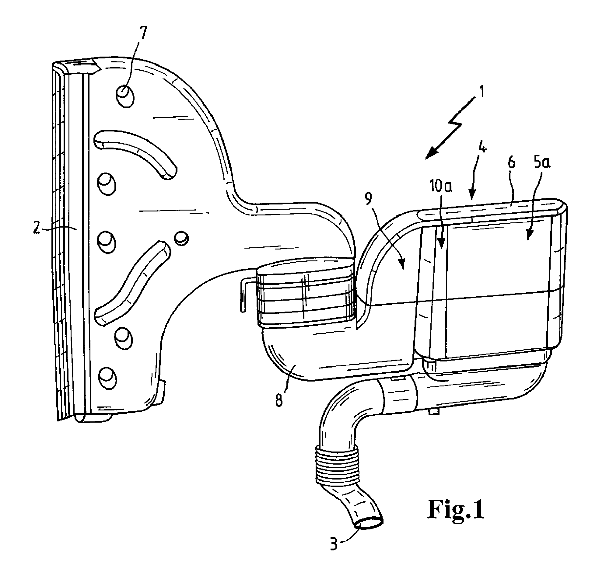
[0039]In FIG. 1, an air inlet system 1 is illustrated that has a raw air inlet 2 and a clean air outlet 3 wherein between the raw air inlet 2 and the clean air outlet 3 a filter element 5 is arranged or inserted in a housing area 4.

[0040]The air to be purified (raw air) flows on its path through the air inlet system 1 first through the raw air inlet 2 that can be attached via penetrations 7, for example, on the car body of a motor vehicle. Then the air flows through an adapter 8 into an inflow area 9 of the filter element 5a, is applied to the filter element 5a, and passes after filtration via the clean air outlet 3 out of the air inlet system 1 and then reaches, for example, an internal combustion engine, not illustrated.

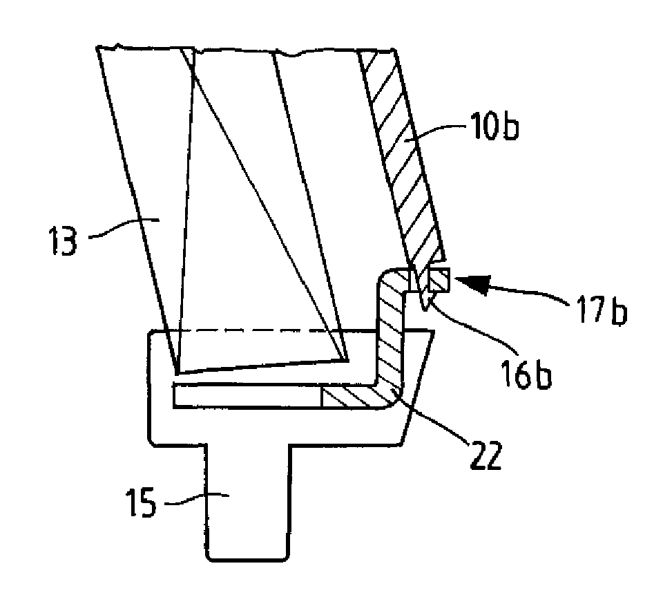
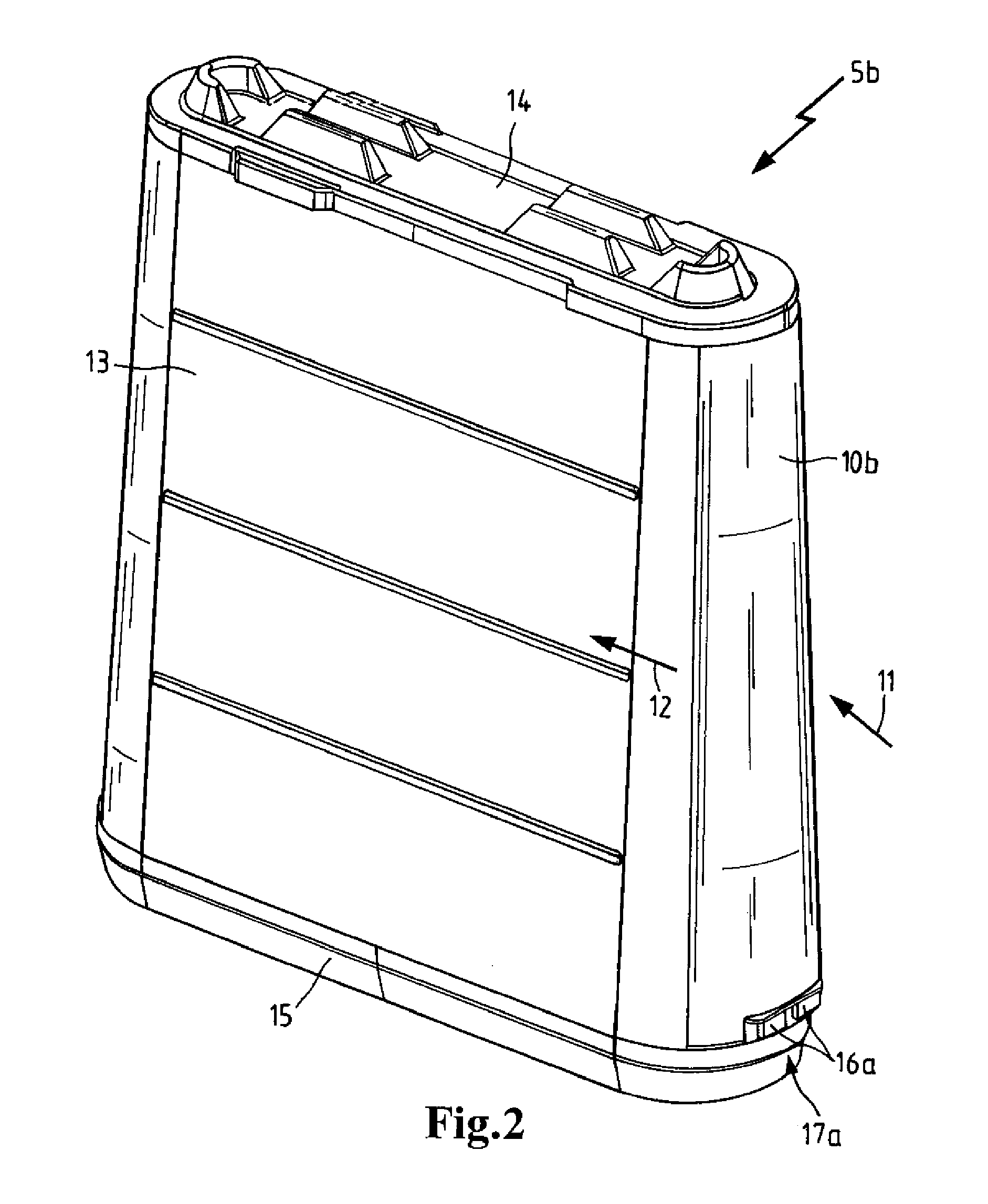
[0041]Immediately before supplying the raw air to the filter element 5a, the raw air impinges in the flow area 5 on an inflow protection element 10a that deflects the inflowing raw air and distributes it uniformly in the housing area 4 in which the filter element 5...


PUM


Abstract

A filter element for an air inlet system includes a filter medium supported on a central tube. An inflow protection element is for flow deflection is arranged in an inflow area of the filter medium. The inflow protection element as well as the central tube and an axial end of the filter medium are embedded into a terminal disk.

Description

CROSS REFERENCE TO RELATED APPLICATIONS[0001]This application is Bypass Continuation of international patent application no. PCT / EP2011 / 068147, filed Oct. 18, 2011 designating the United States of America, the entire disclosure of which is incorporated herein by reference. Priority is claimed based on German patent application no. 10 2010 049 411.9 filed Oct. 26, 2010.TECHNICAL FIELD[0002]The invention concerns a filter element for an air inlet system that comprises a filter medium, in particular in the form of a bellows, for purifying raw air as well as a central tube for supporting the filter medium. Filter elements are used for purifying gaseous substances or substance mixtures, for example, air, and are used, for example, in the automotive industry in air inlet systems of internal combustion engines. The filter medium that can be, for example, a paper filter in the form of a bellows retains contaminants that are contained in the air to be purified. Typically, the contaminants ar...

Claims


Application Information

Patent Timeline
Patent Type & Authority Patents(United States)
IPC IPC(8): B01D50/00B01D46/24B01D46/00F02M35/024F02M35/04
CPCB01D46/0043B01D50/002F02M35/02491F02M35/044B01D2275/208B01D50/20
Inventor HEIM, MICHAELNEEF, PASCALSUDERMANN, ARTHURBLOSSEY, WERNERFRITZSCHING, TORSTEN
Owner MANN HUMMEL GMBH
Why Eureka
Try Eureka