Guiding device and guiding method for diesel engine selective catalytic reduction (SCR) system for automobile

A technology of SCR system and diversion device, which is applied in the direction of mufflers, exhaust devices, mechanical equipment, etc., can solve the problem of affecting the power and economy of diesel engines, insufficient use of edge areas, and large radial temperature and pressure gradients To achieve the effect of improving the passing capacity and utilization rate of the catalyst, reducing the flow sharing rate, and weakening the flow separation

Inactive Publication Date: 2013-05-08
JIANGSU UNIV
View PDF8 Cites 8 Cited by
  • Summary
  • Abstract
  • Description
  • Claims
  • Application Information

AI Technical Summary

Problems solved by technology

[0004] SCR technology is being promoted and applied all over the world, but to achieve the best purification effect, several shortcomings need to be overcome: after the air flow enters the expansion tube, flow separation occurs along the wall surface, forming a large stagnation area; the catalytic converter The gas flow rate in the interior is uneven, and the air flow is mainly concentrated in the central area of ​​the carrier, which causes the catalyst in the central area to age at high temperature, while the edge area is not fully utilized, which affects the service life of the catalyst; at the same time, the uneven flow rate will also cause the catalyst carrier radial direction Excessive temperature and pressure gradients will cause large thermal fatigue damage and affect the power and economy of diesel engines

Method used


Image

  • Guiding device and guiding method for diesel engine selective catalytic reduction (SCR) system for automobile
  • Guiding device and guiding method for diesel engine selective catalytic reduction (SCR) system for automobile
  • Guiding device and guiding method for diesel engine selective catalytic reduction (SCR) system for automobile

Examples


Embodiment Construction

[0030] The present invention will be described in further detail below in conjunction with the accompanying drawings.

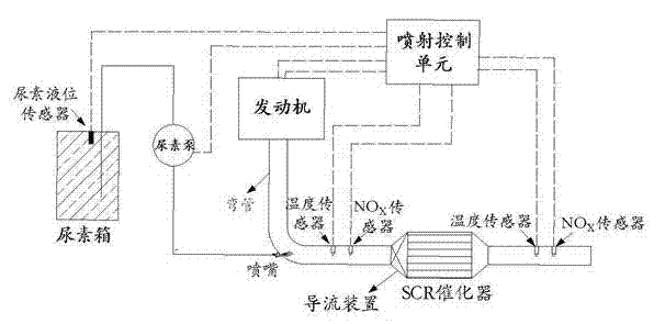
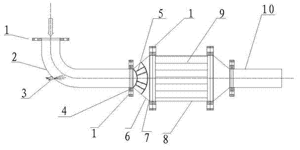
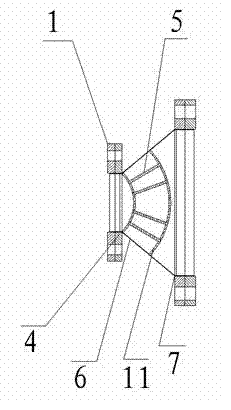
[0031] Diesel engine urea SCR system such as figure 1 with figure 2 As shown, the present invention is installed between the SCR catalytic converter 8 and the bend pipe 2, and its specific structure is as follows: Figure 3 to Figure 6 shown.

[0032] The present invention is a deflector device for the SCR system of a diesel engine for a vehicle, comprising an expansion tube 6 and at least two deflector plates 5 nested with each other. One end of the pipe 6 is the air outlet 7, the inlet end 4 of the expansion pipe 6 is connected with the elbow 2, the deflector 5 is fixedly arranged on the front end of the expansion pipe 6, and its shape is a trumpet shape without front and rear end faces. A fluid channel 12 is formed between them. The quantity of deflector plate 5 is preferably 2 to 4 pieces, and the length of deflector plate 5 is preferably 1 / 3 to 2 / 3 ...


PUM


Abstract

The invention relates to a guiding device and a guiding method for a diesel engine selective catalytic reduction (SCR) system for an automobile. The guiding device comprises an expansion pipe and at least two guiding plates arranged in a mutually embedding mode. The end where gas flows to the expansion pipe is a gas inlet end and the end where the gas flows out of the expansion pipe is a gas output end. The guiding plates at fixedly arranged on the gas inlet end of the expansion pipe and each guiding plate is in a trumpet shape without a front end face and a rear end face. A fluid channel is formed among the guiding plates. The guiding device is simple in structure, low in manufacturing cost and easy to install. According to the guiding device and the guiding method, due to backflow generated in the portion of an elbow pipe, exhaust of the automobile and urea sprayed from a nozzle can mix well so that generation of crystal on a wall is reduced. Due to the guiding device in the expansion pipe portion, mixed gas is converted from turbulent flow to laminar flow so that velocity distribution is even, radial pressure difference and temperature difference inside a catalytic agent are reduced, conversion efficiency of nitric oxides is improved, through capacity of a catalytic agent carrier is improved and service life of a catalyst is prolonged.

Description

technical field [0001] The patent of the present invention relates to the field of exhaust systems of diesel engines for vehicles, and more specifically relates to a flow guide device and method for SCR systems of diesel engines for vehicles. Background technique [0002] Diesel engine is famous for its fuel economy, power, reliability and CO 2 Low emissions are favored by people, but there is a big problem with diesel engines, which is the emission problem, which brings a lot of NOX and PM emissions and causes serious environmental pollution. With the increasingly stringent emission regulations, the emission control of diesel engines is still one of the key challenges in diesel engine applications. [0003] There are two different routes for exhaust after-treatment technology for diesel engines to meet the requirements of my country's upcoming National IV emission regulations: one is the exhaust gas recirculation + particulate filter route represented by the United States;...

Claims


Application Information

Patent Timeline
Patent Type & Authority Applications(China)
IPC IPC(8): F01N3/28F01N3/20
CPCY02T10/24Y02A50/20Y02T10/12
Inventor 李硕何志霞王谦王静李建治张州榕
Owner JIANGSU UNIV
Why Eureka
Try Eureka