Oil cooler

An oil cooler and oil cooling technology, which is applied to indirect heat exchangers, heat exchanger shells, heat exchanger types, etc., can solve the problems of oil cooler heat dissipation performance degradation and other issues

Active Publication Date: 2012-03-21
DENSO CORP
View PDF5 Cites 9 Cited by
  • Summary
  • Abstract
  • Description
  • Claims
  • Application Information

AI Technical Summary

Problems solved by technology

[0008] Therefore, if the specifications for the offset fins for the oil cooler are simply applied to the specifications for the EGR cooler or the intercooler, the heat dissipation performance of the oil cooler may be reduced.

Method used


Image

  • Oil cooler
  • Oil cooler
  • Oil cooler

Examples


Embodiment Construction

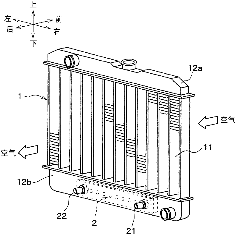
[0036] figure 1 It is a perspective view showing the radiator 1 incorporating the oil cooler 2 of this embodiment. Such as figure 1 As shown, the radiator 1 of this embodiment has a plurality of radiator pipes 11 made of aluminum through which the engine cooling water flows, and aluminum pipes 11 arranged on both ends in the longitudinal direction of the radiator pipes 11 and communicating with the plurality of radiator pipes 11 . Made of the first radiator tank 12a and the second radiator tank 12b.

[0037] The first radiator tank 12 a is connected to the longitudinal upper ends of the plurality of radiator pipes 11 , and distributes engine cooling water to the plurality of radiator pipes 11 . In addition, the second radiator tank 12 b is connected to the lower ends in the longitudinal direction of the plurality of radiator pipes 11 , so that the engine cooling water flowing out from the plurality of radiator pipes 11 is collected.

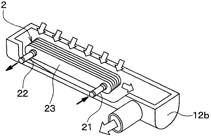
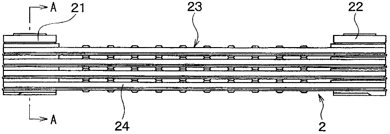
[0038] In the second radiator tank 12b,...


PUM


Abstract

An oil cooler comprises an inner fin 3, an offset fin, having a wavy cross-section that is perpendicular to an oil flowing direction, and has a louver 32 that is partially cut and bent in a direction parallel with the oil flowing direction. The wavy cross-section is defined by alternately placing first-side convex parts 31 and second-side convex parts. A fin height fh is defined by a distance from the first-side convex part 31 to the second-side convex part 31 in the cross-section. An area C surrounded by the inner fin 3, a tube 24, and the first-side or second-side convex parts 31 located adjacent with each other on the same side in the cross-section is converted into a corresponding circle having a diameter de. When a relationship of X=de / fh0.3 is defined, the diameter of the corresponding circle and the fin height respectively have dimensions that satisfy a relationship of 0.5<=X<=1.0.

Description

technical field [0001] The present invention relates to an oil cooler for cooling engine oil of a vehicle, operating fluid (ATF) for an automatic transmission, and the like. Background technique [0002] At present, the oil cooler built in the tank of the radiator is configured by stacking a plurality of tubes for supplying oil, and passing between the oil flowing inside the tubes and the cooling water flowing outside the tubes. Heat exchange to cool the oil. In addition, inner fins (inner fins) are arranged inside the tubes to promote heat exchange between the oil and the cooling water. [0003] In the oil cooler configured in this way, appropriate heat dissipation performance can be ensured by increasing the number of tubes in response to an increase in the required heat dissipation amount. Here, the size of the radiator tank is inevitably determined by the size of the oil cooler. Therefore, in order to reduce the thickness and weight of the radiator tank, it is necessar...

Claims


Application Information

Patent Timeline
Patent Type & Authority Applications(China)
IPC IPC(8): F28D1/04F28F1/40F01M5/00
CPCF28F9/0234F28D9/0043F28D2021/0089F28F3/027
Inventor 宇野孝博长贺部博之高桥大辅
Owner DENSO CORP
Why Eureka
Try Eureka