Rotary actuator

a technology of rotary actuators and actuators, which is applied in the direction of mechanical equipment, machines/engines, and gears, etc., can solve the problems of difficult suppression of leakage of pressure fluid in the rotary sliding portion, leakage of pressure fluid and leakage of pressure fluid between the grooves and the seals, so as to reduce internal leakage of the pressure medium within the rotary actuator. , the effect of reducing the internal leakage of the pressure medium

Active Publication Date: 2015-09-15
NABLESCO CORP
View PDF11 Cites 10 Cited by
  • Summary
  • Abstract
  • Description
  • Claims
  • Application Information

AI Technical Summary

Benefits of technology

[0011]In light of the foregoing circumstance, it is an object of the present invention to provide a rotary actuator capable of reducing internal leakage of the pressure medium, and whose structure does not need the high-pressure rotary seals.
[0024]With this configuration, among the plurality of piston units, the number of the piston units that generate urging force applied to the arm can be changed to drive the arm, and it is therefore possible to easily achieve the structure of the rotary actuator with which the output is variable.

Problems solved by technology

Unfortunately, it is difficult to suppress leakage of the pressure fluid in the rotary sliding portions by means of the seals.
Therefore, the pressure fluid often leaks within the rotary actuator.
Moreover, the conventional rotary actuators have a structure in which the seals are inserted into the grooves in the ribs or the vanes, the problem of leakage between the grooves and the seals also arises.
Furthermore, since each seal inserted into the groove has corner sections, it is particularly difficult to maintain adhesion to the surface relative to which the seal slides, in those corner sections and in the vicinity thereof, which makes it difficult to suppress leakage.
Therefore, the pressure fluid leaks more often within the rotary actuator.
In addition, the conventional rotary actuators need high-pressure rotary seals that are used in the rotary sliding portions and pressed with high pressure against the surface relative to which the seals slide.
Such seals are therefore different from statically used seals or those for use in linear sliding portions, and another problem arises of significantly shorter duration of the seals during which sealing characteristics intended by the design can be maintained.

Method used


Image

  • Rotary actuator
  • Rotary actuator
  • Rotary actuator

Examples


Embodiment Construction

[0037]Embodiments for implementing the present invention will be hereinafter described with reference to the drawings. Note that the present invention can be applied broadly to rotary actuators that output driving torque as a result of output shafts pivoting in a rotational direction due to action of a pressure medium.

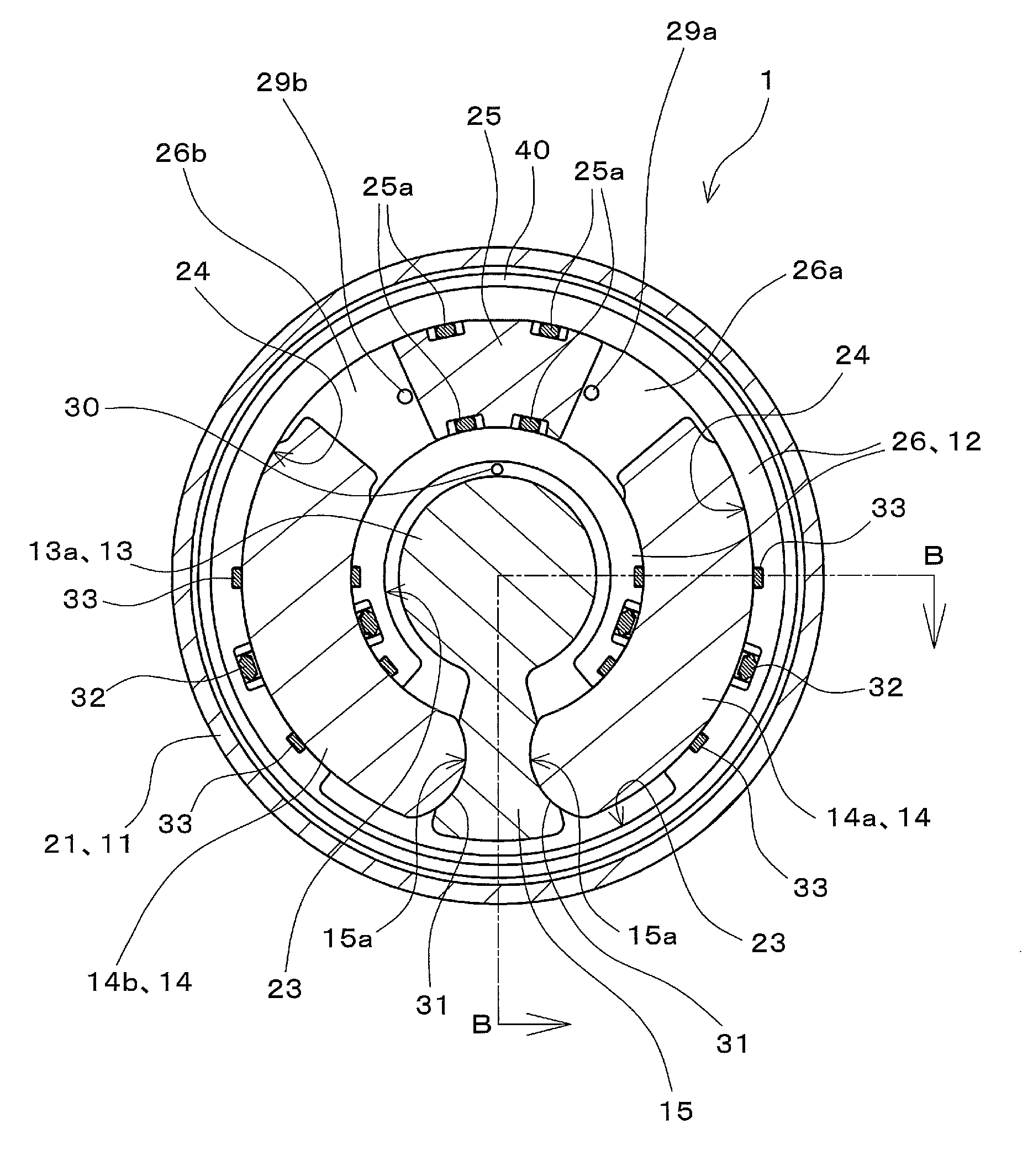
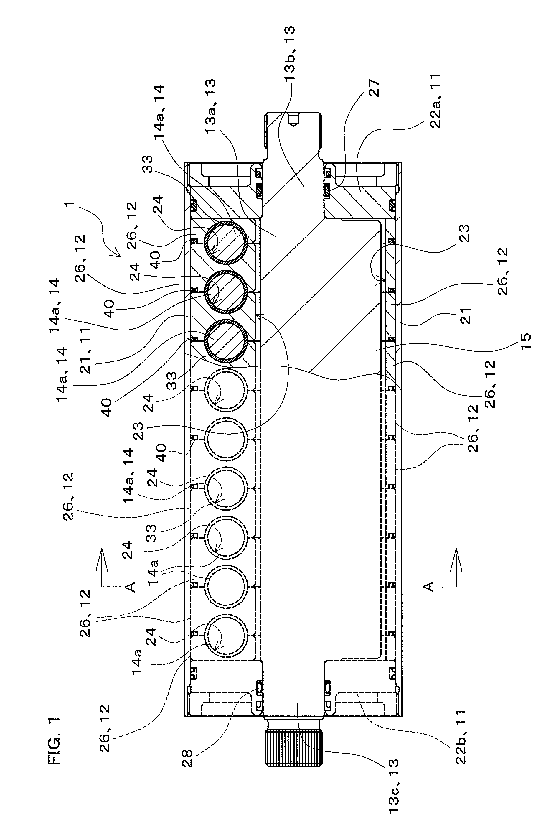
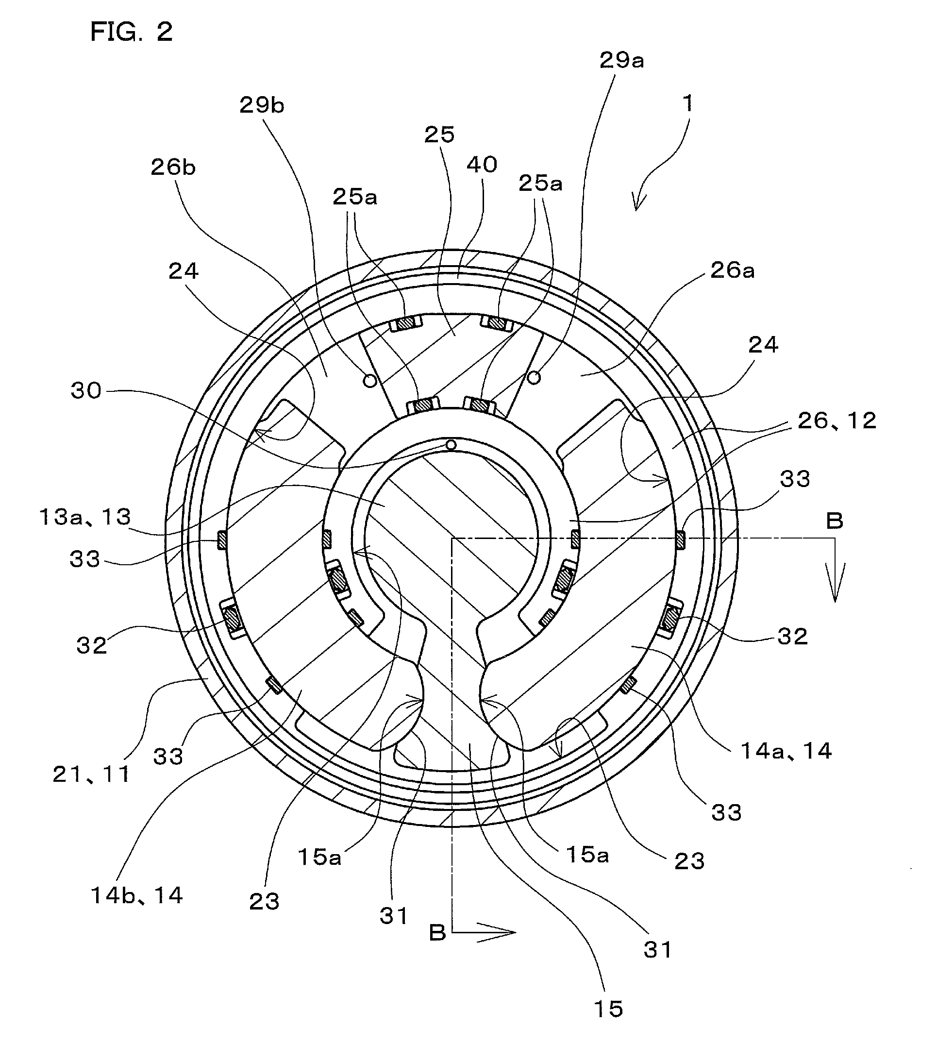
[0038]FIG. 1 is a diagram showing a rotary actuator 1 according to one embodiment of the present invention including a partial cross-sectional view thereof, viewed from a direction perpendicular to an axial direction thereof. FIG. 2 is a cross-sectional view of the rotary actuator 1, viewed along arrows A-A FIG. 1. Note that FIG. 1 includes the cross section viewed along arrows B-B in FIG. 2.

[0039]The rotary actuator 1 shown in FIGS. 1 and 2 is provided as an actuator that outputs driving torque as a result of an output shaft 13 pivoting in a rotational direction around its shaft center due to action of a pressure medium. The pressure medium can be various kinds of pre...


PUM


Abstract

A cylinder is installed within a case. An output shaft is installed in a hollow space within the cylinder. A pair of pistons extend in an arc, and is supported so as to be able to slide and be displaced along a circumferential direction of the cylinder within the cylinder. The pair of pistons is able to urge an arm integrated with the output shaft from two sides of the arm. Pressure chambers into which a pressure medium is introduced are defined between the cylinder and each piston in the pair of pistons. The pressure medium is fed to one of the pressure chambers and drained from the other, and thus the arm is displaced, and the output shaft pivots in a rotational direction.

Description

CROSS-REFERENCE TO RELATED APPLICATION[0001]This application claims priority to Japanese Patent Application No. 2011-238213. The entire disclosure of Japanese Patent Application No. 2011-238213 is hereby incorporated herein by reference.BACKGROUND OF THE INVENTION[0002]1. Field of the Invention[0003]The present invention relates to rotary actuators that output driving torque as a result of output shafts pivoting in a rotational direction due to action of a pressure medium.[0004]2. Description of the Related Art[0005]A rotary actuator having such a configuration as the one disclosed in U.S. Pat. No. 5,601,165 is known as one of the rotary actuators that output driving torque as a result of an output shaft pivoting in a rotational direction due to action of a pressure fluid serving as a pressure medium.[0006]In the rotary actuator disclosed in U.S. Pat. No. 5,601,165, ribs are provided within a cylinder as an integral unit, and vanes are provided to an output shaft rotatably installed...

Claims


Application Information

Patent Timeline
Patent Type & Authority Patents(United States)
IPC IPC(8): F16H29/02F01C9/00F01C1/063
CPCF16H29/02F01C1/063F01C9/002F15B15/125
Inventor ITO, KOJIKOIZUMI, TAKASHI
Owner NABLESCO CORP
Why Eureka
Try Eureka