Flow separation, pressure adjustment and speed adjustment reversing integrated valve

A technology of pressure regulation and speed regulation, integrated valve, applied in the direction of fluid pressure actuation device, servo motor assembly, mechanical equipment, etc., can solve the problems of high manufacturing cost and failure rate, waste of energy, temperature rise of working medium, etc. And the effect of reducing operation and maintenance costs, reducing system failure rate, and solving excessive temperature rise

Active Publication Date: 2018-08-17
河北华春液压汽配有限公司
View PDF7 Cites 6 Cited by
  • Summary
  • Abstract
  • Description
  • Claims
  • Application Information

AI Technical Summary

Problems solved by technology

[0017] The main problems in the above-mentioned prior art are: firstly, because the flow rate of the quantitative duplex pump is preset and cannot be adjusted, when the working conditions in the operating environment change, it cannot be adjusted adaptively, and the matching is poor; the second is that the quantitative duplex gear Due to the complex structure of the pump, its manufacturing cost and failure rate are high; the third is that when one pump in the quantitative double pump is in the working state, although the other pump is in the non-working state, it still runs dry and generates reactive power loss. While wasting energy, it causes temperature rise of the working medium
[0019] The main problems in the above-mentioned prior art are: first, the variable control of the variable pump is completed by transmitting the measured value of the sensor to the control device and issuing corresponding instructions, so the structure is complicated and the cost is high; second, the variable pump can only realize displacement adjustment , cannot control the pressure, so it is necessary to equip each actuator with a pressure control element (such as a relief valve) to meet the load requirements of different qualities, and at the same time, it is necessary to add control elements and pipelines to avoid pressure interference in the circuits of different actuators; 3. It is because the plunger pump has high requirements for the cleanliness of the working medium, which leads to high requirements for the level of system components and high operation and maintenance costs.
[0021] The main problems in the above-mentioned prior art are: firstly, the flow adjustment is realized by changing the diameter area of ​​the throttle valve, and the execution pressure changes with the change of the load. The pressure is a set value, which will inevitably cause the pressure difference on both sides of the throttle valve to be too large, which will convert the pressure difference energy into heat energy and cause oil temperature rise and energy consumption; the second is that the oil pump is always in a high pressure state It will cause a huge energy consumption due to the operation at low pressure, and the service life of the oil pump will be greatly shortened; third, because the relief valve can only be installed in the main circuit with relatively high pressure, it can only meet the working conditions under the set pressure value
[0022] The applicant did not find any patent literature reports identical or similar to this application after searching

Method used


Image

  • Flow separation, pressure adjustment and speed adjustment reversing integrated valve
  • Flow separation, pressure adjustment and speed adjustment reversing integrated valve
  • Flow separation, pressure adjustment and speed adjustment reversing integrated valve

Examples


Embodiment Construction

[0058] The present invention will be further described below in conjunction with the examples, but it should not be interpreted as a limitation of the present invention. The protection scope of the present invention is based on the contents recorded in the claims. protection scope of the present invention.

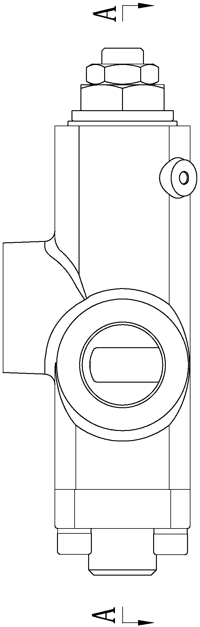
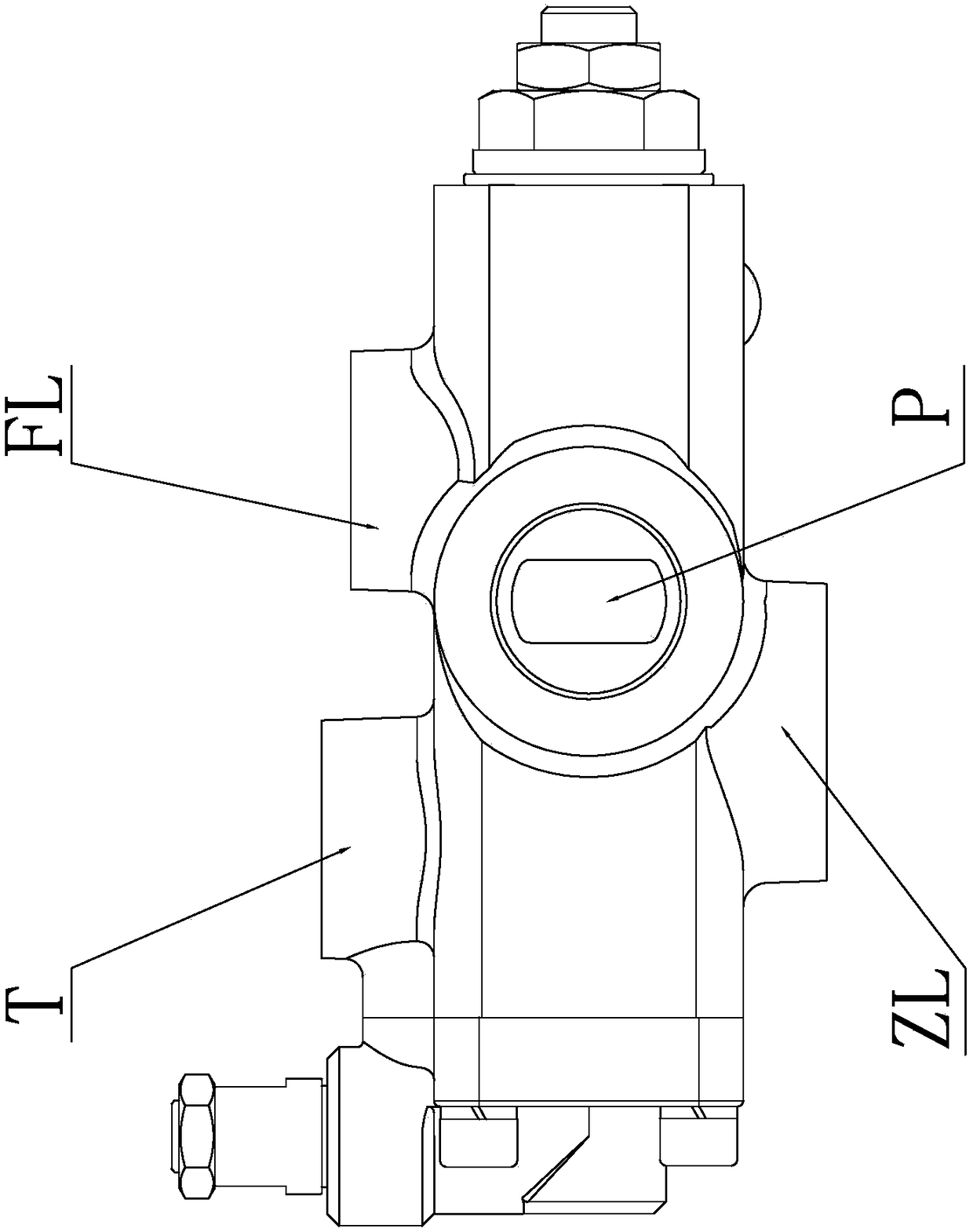
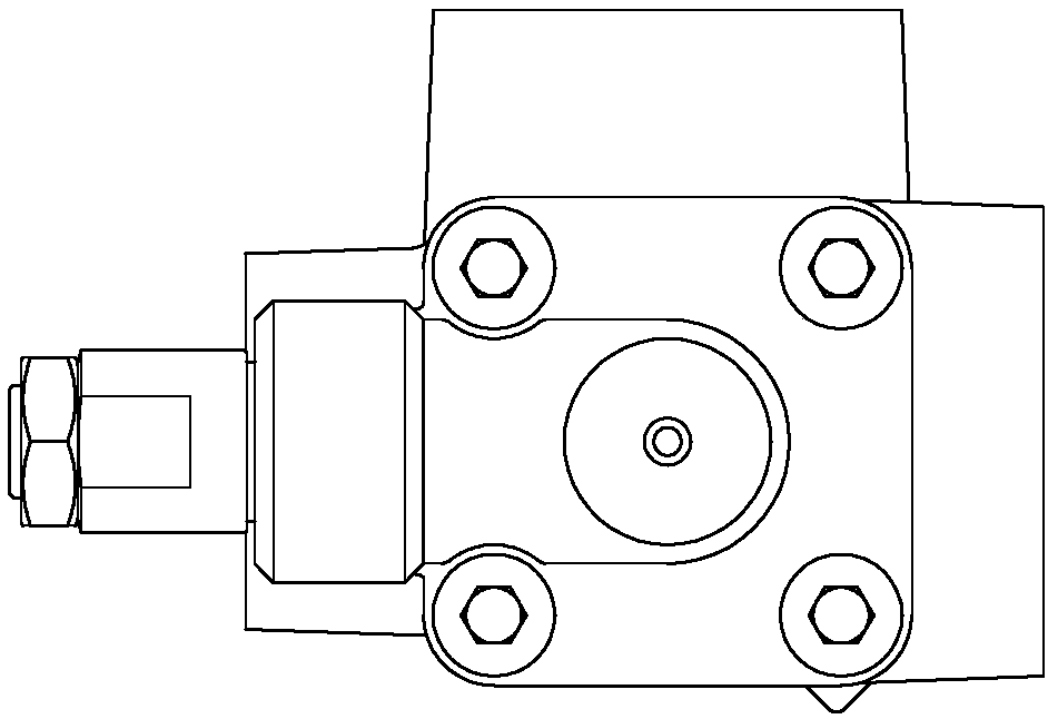
[0059] The overall structure of this embodiment is shown in the figure, which includes a valve body 10, an oil inlet P opened on the valve body 10, the oil inlet P is connected to the oil inlet chamber PQ, and a relief valve is inserted on the valve body 10; 10 is provided with an oil return port T, a throttle oil outlet FL, and an oil outlet ZL. The valve body 10 is successively separated from left to right with an overflow back pressure chamber BQ and an oil outlet chamber ZQ axially penetrated by the main hole 4. , oil inlet chamber PQ, fuel saving oil outlet chamber FQ, hydraulic control chamber YQ; throttle outlet chamber FQ connects with throttle outlet FL, oil outle...


PUM


Abstract

The invention belongs to a valve, in particular to a flow separation, pressure adjustment and speed adjustment reversing integrated valve. The integrated valve comprises a valve body, an oil inlet andoverflow valve arranged on the valve body, and a pilot pressure adjusting, throttling switching and speed adjusting unit; the valve body is provided with an oil return port, a throttling oil outlet and an oil outlet; an overflow back pressure cavity, an oil outlet cavity, an oil inlet cavity, a throttling oil outlet cavity and a liquid control cavity, axially penetrating through a main hole, arearranged in the valve body at intervals; the throttling oil outlet cavity communicates with the throttling oil outlet; the oil outlet cavity communicates with the oil outlet; the oil outlet cavity communicates with the liquid control cavity by a liquid control hole way; an overflow main valve sleeve is inserted in the main hole to form dynamic seal fit, the outer end thereof is assembled with an outer end stop port of the main hole, and the inner end thereof is provided with a throttling port; and in a non-working state, the overflow main valve sleeve separates the oil inlet cavity from the oil outlet cavity. The integrated valve effectively solves the technical difficulties of high energy consumption, high working medium temperature rise and the like in the prior art, and has the advantages of capability of respectively driving multiple execution elements with different working pressures and flows, lower grade requirement on system modules, capability of realizing speed adjustment andthe like.

Description

technical field [0001] The invention belongs to valves, in particular to an integrated valve for flow diversion, pressure regulation, speed regulation and reversing. Background technique [0002] The existing hydraulic transmission system or mobile hydraulic mechanical system requires more than two working systems, and the flow and working pressure required by each working system have different settings. More than one actuator supplies the same flow (equal split flow), or supplies flow to two actuators in a certain proportion (proportional split flow), so as to realize the synchronization or proportional relationship between the speeds of the two actuators. [0003] Traditional hydraulic systems include: [0004] 1. Power components [0005] The function of the power element is to convert the mechanical energy of the prime mover into the pressure energy of the liquid, which refers to the oil pump in the hydraulic system, which provides power to the entire hydraulic system....

Claims


Application Information

Patent Timeline
Patent Type & Authority Applications(China)
IPC IPC(8): F15B13/02
CPCF15B13/02F15B13/022
Inventor 郑玉涛黄建安
Owner 河北华春液压汽配有限公司
Why Eureka
Try Eureka