Piston hinge-type variable-displacement vane pump

A variable displacement vane pump, articulated technology, applied in rotary piston pumps, rotary piston machines, pumps, etc., can solve the problems of large internal frictional resistance, insignificant fuel saving effect, inflexible space layout, etc. Small internal friction resistance, easy to three-level variable, small effect of cavitation

Active Publication Date: 2015-06-03
苏州引燃动力科技有限公司
View PDF8 Cites 6 Cited by
  • Summary
  • Abstract
  • Description
  • Claims
  • Application Information

AI Technical Summary

Problems solved by technology

[0011] (1) Large fluctuations in oil pressure;
[0012] (2) Large internal leakage;
[0013] (3) Non-metallic seals are used inside, which has low reliability;
[0016] (6) Inflexible space arrangement; and
[0017] (7) Large internal frictional resistance
[0018] However, the conventional vane-type variable pump casing can only achieve one-stage variable, the fuel-saving effect is not obvious, and it also has most of the defects of the above-mentioned improvements.

Method used


Image

  • Piston hinge-type variable-displacement vane pump
  • Piston hinge-type variable-displacement vane pump
  • Piston hinge-type variable-displacement vane pump

Examples


no. 1 example

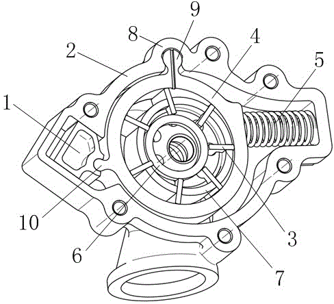
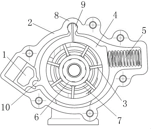
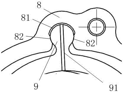
[0080] Such as Figures 1 to 5 As shown, the first embodiment of the present invention provides a piston articulated variable displacement vane pump comprising two control chambers. Here, the pump housing 2 contains a pump chamber with an inlet and an outlet. A pump cover (not shown in the figure) covers the pump casing 2 . The pump control ring 4 moves in the pump chamber to adjust the capacity of the oil pump. The vane pump rotor 7 is rotatably arranged in the pump control ring 4 , and the rotation axis of the vane pump rotor 7 deviates from the center of the pump control ring 4 . The vane ring 6 is rotatably arranged in the vane pump rotor 7 , and the vane ring 6 rotates around the center of the vane pump rotor 7 . Seven blades 3 (not limited to seven, can also be other numbers), slidably pass through the vane pump rotor 7 respectively, the inner ends of the blades 3 abut against the outer surface of the blade ring 6, and the outer end abuts the inner surface of the pum...

no. 2 example

[0091] Such as Figures 6 to 11 As shown, the second embodiment of the present invention provides a piston articulated variable displacement vane pump, which is different from the first embodiment in that the second embodiment can contain at most three control chambers. Here, the pump housing 2 contains a pump chamber with an inlet and an outlet. A pump cover (not shown in the figure) covers the pump casing 2 . The pump control ring 4 moves in the pump chamber to adjust the capacity of the oil pump. The vane pump rotor 7 is rotatably arranged in the pump control ring 4 , and the rotation axis of the vane pump rotor 7 deviates from the center of the pump control ring 4 . The vane ring 6 is rotatably arranged in the vane pump rotor 7 , and the vane ring 6 rotates around the center of the vane pump rotor 7 . Seven blades 3 (not limited to seven, can also be other numbers), slidably pass through the vane pump rotor 7 respectively, the inner ends of the blades 3 abut against the...


PUM


Abstract

The invention discloses a piston hinge-type variable-displacement vane pump. The vane pump comprises a pump shell, a pump cover, a pump control loop, a vane pump rotor, a vane loop and a plurality of vanes, wherein the outer surface of the pump control loop is provided with a first hinge bulge, the first hinge bulge is positioned on a hinge positioning hole of the inner surface of the pump shell, and the pump control loop swings by taking the hinge positioning hole as a base point, so that the volume capacity of the vane pump is changed, the outer surface of the pump control loop and one side of the first hinge bulge are provided with a second hinge bulge, and a piston is hinged with the second hinge bulge; a first control cavity is formed between the piston and the partial inner surface of the pump shell, the first control cavity is capable of introducing a pressurized fluid to generate pressure to move the pump control, so as to decrease the volume capacity of the vane pump, the outer surface of the pump control loop and the other side of the first hinge bulge prop against a reset spring, the reset spring resists the force of the first control cavity, so as to establish balance. The piston hinge-type variable-displacement vane pump is high in reliability, easy for realization of three-stage variable capability, long in force arm length, and small in inner frictional resistance.

Description

technical field [0001] The invention relates to the field of variable-displacement vane pumps, in particular to a piston hinged variable-displacement vane pump. Background technique [0002] The inner surface of the stator of the variable vane pump is a circle, and there is an eccentric distance between the rotor and the stator. There is only one oil suction window and one oil pressure window on the oil distribution plate. When the rotor is driven by the motor and rotates in the direction of the arrow in the figure, when the blade passes through the lower half of the stator, under the action of centrifugal force, it protrudes from the blade groove, and the sealing volume between the two blades increases to realize oil absorption; the blade passes through the stator In the upper half, it is gradually pressed into the vane groove by the inner surface of the stator, and the sealing volume is reduced to realize oil pressure. Every time the rotor of the pump rotates, each seali...

Claims


Application Information

Patent Timeline
Patent Type & Authority Applications(China)
IPC IPC(8): F04C14/18F04C2/344F16N13/20
CPCF04C2/344F04C14/18
Inventor 王光明荀生平
Owner 苏州引燃动力科技有限公司
Why Eureka
Try Eureka