
An oil circuit pressure control device and control method thereof

A pressure control and oil circuit technology, applied in pump control, mechanical equipment, machine/engine, etc., can solve problems such as inflexible design space, easy to generate noise, large oil pressure fluctuations, etc., achieve low noise, reduce pollution emissions, The effect of small oil pressure fluctuation

Inactive Publication Date: 2018-01-23
周丹丹
View PDF10 Cites 0 Cited by
  • Summary
  • Abstract
  • Description
  • Claims
  • Application Information

AI Technical Summary

Problems solved by technology

[0003] However, the above technology still has the following defects: 1. The oil pressure fluctuates greatly, which is easy to generate noise; 2. The pressure generated under different temperatures varies greatly, which will cause energy waste and pollution; 3. The design space is not flexible

Method used


Image

  • An oil circuit pressure control device and control method thereof
  • An oil circuit pressure control device and control method thereof
  • An oil circuit pressure control device and control method thereof

Examples


Embodiment 1

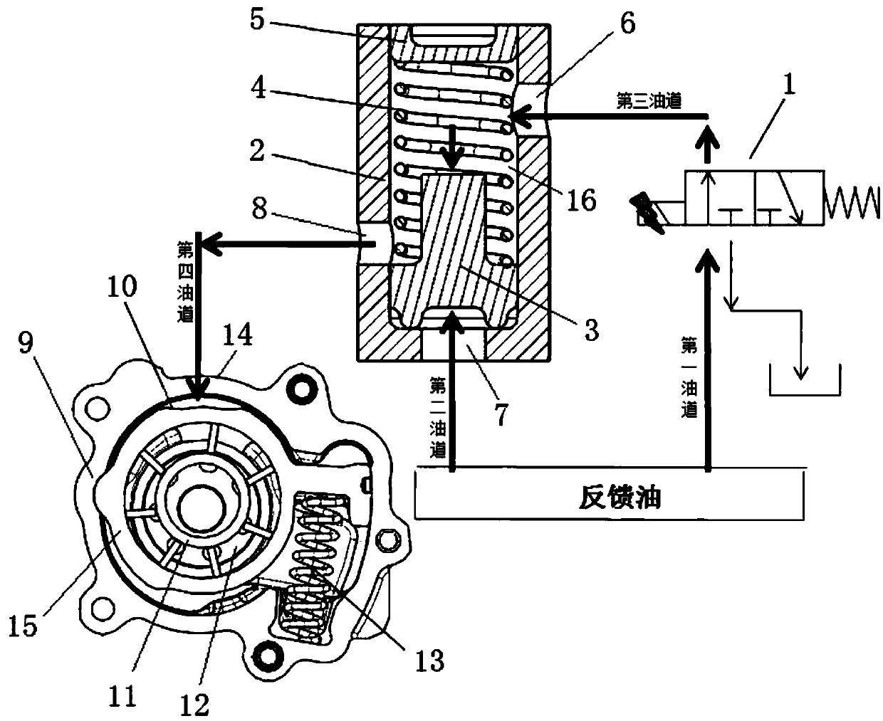
[0066] See figure 1 , figure 2 , an oil circuit pressure control device provided by the present invention includes an engine, a solenoid valve 1, a variable displacement pump, and an oil pump.

[0067] The oil pump comprises an oil pump housing 2, a bottom piston 3, a first spring 4, and a top piston 5, and the bottom piston 3 and the top piston 5 have the same maximum cross-sectional area. Three oil holes are provided on the oil pump housing 2 , namely a first oil hole 6 , a second oil hole 7 and a third oil hole 8 .

[0068] The bottom piston 3, the first spring 4 and the top piston 5 are located in the oil pump housing 2, the first spring 4 is installed between the bottom piston 3 and the top piston 5, and a spring is formed between the bottom piston 3, the top piston 5 and the oil pump housing 2 Cavity 16.

[0069] The variable displacement pump includes a casing 9 , a pump control ring 15 , a vane ring 11 , a vane pump rotor 12 , a second spring 13 , and a fourth oil ...

Embodiment 2

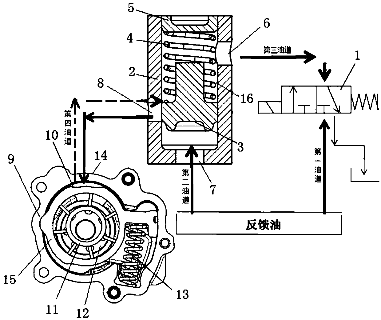
[0084] See image 3 , Figure 4 , an oil circuit pressure control device provided by the present invention includes an engine, a solenoid valve 1, a variable displacement pump, and an oil pump.

[0085] The oil pump comprises an oil pump housing 2, a bottom piston 3, a first spring 4, and a top piston 5, and the bottom piston 3 and the top piston 5 have the same maximum cross-sectional area. Three oil holes are arranged on the oil pump casing 2, which are respectively the first oil hole 6, the second oil hole 7, the third oil hole 8, and the oil pump outlet.

[0086] The bottom piston 3, the first spring 4, and the top piston 5 are located in the oil pump housing 2, the bottom piston 3 is installed below the top piston 5, the first spring 4 is installed below the bottom piston 3, the bottom piston 3 and the oil pump housing 2 A spring cavity 16 is formed therebetween.

[0087] The variable displacement pump includes a casing 9, a pump control ring 15, a vane ring 11, a vane...


PUM


Abstract

The invention discloses an oil way pressure control device. The oil way pressure control device comprises an engine, an electromagnetic valve (1), a variable displacement pump and an oil pump; the oil pump includes an oil pump shell (2), a bottom piston (3), a first spring (4) and a top piston (5); three oil holes are formed in the oil pump shell (2), and are respectively a first oil hole (6), a second oil hole (7) and a third oil hole (8); the variable displacement pump includes a shell (9), a pump control ring (15), a blade ring (11), a blade pump rotor (12), a second spring (13) and a fourth oil hole (14); and a control cavity (10) is formed between the shell (9) and the pump control ring (15). The oil way pressure control device is flexible in design, convenient for installation, variable in design of the pistons in the oil pump and capable of satisfying different client demands, can realize two-grade pressure or multistage pressure, satisfies the engine oil saving requirement, improves the engine economy, and reduces the pollutant discharge to protect the environment.

Description

technical field [0001] The invention relates to the field of pump control, in particular to an oil circuit pressure control device and a control method thereof. Background technique [0002] Chinese patent (CN100520069C) discloses a variable vane pump with double control chambers, the pump has a pump control ring that can be moved to change the pump capacity, and a return spring between the pump control ring and the pump housing, a first control chamber and a second control chamber, the return spring acts against the forces of the first and second control chambers to establish a balanced pressure, and wherein the supply of pressurized fluid to the second control chamber can be applied or removed to vary the pump's Balance stress. [0003] However, the above technology still has the following defects: 1. The oil pressure fluctuates greatly, which is easy to generate noise; 2. The pressure generated under different temperatures varies greatly, which will cause energy waste an...

Claims


Application Information

Patent Timeline
Patent Type & Authority Patents(China)
IPC IPC(8): F04C14/00
CPCF04C14/00
Inventor 不公告发明人
Owner 周丹丹
Learn More