Function regulation and control structure production method based on continuous fiber composite material 3D printing

A 3D printing and continuous fiber technology, applied in the field of functional control structure preparation based on continuous fiber composite 3D printing, to meet the preparation requirements, improve mechanical properties, and good applicability

Active Publication Date: 2017-12-05
深圳协同创新高科技发展有限公司
4 Cites 33 Cited by

AI-Extracted Technical Summary

Problems solved by technology

However, the existing continuous fiber-reinforced thermoplastic composite material 3D printing process only realizes the manufacture of simple composite material components, and has not comprehensively considered how to integrate with the fiber direction and function control des...

Method used

1) set up three-dimensional model: according to the size and data of Fig. 2, utilize computer-aided design CAD software Solidworks, according to the profile feature of fiber composite material part, set up the three-dimensional model of...

Abstract

The invention relates to a function regulation and control structure production method based on continuous fiber composite material 3D printing, computer aided design software is used, according to the profile characteristic of a function regulation and control structure material product, a product three-dimensional model is established, then a corresponding performance analysis is carried out on the product by the computer aided design software, the function regulation and control design is carried out on the key characteristic areas, a fiber track curve is drafted, then the fiber track is subjected to algorithm optimization, the technical means during 3D printing is considered, the fiber track is adjusted to obtain the final fiber track curve, according to the track curve, a 3D printing path instruction file of the product is generated, and the instruction file is introduced into a continuous fiber reinforced composite material 3D printer, and the preparation of the function regulation and control structural material is completed. The method can realize dynamic control of fiber path and content in the composite material, and designability manufacture of the function regulation and control materials such as a variable stiffness fiber composite material, a thermal-conduction controllable material and a electromagnetic controllable material can be completed.

Application Domain

Technology Topic

Three dimensional modelComputer Aided Design +13

Image

  • Function regulation and control structure production method based on continuous fiber composite material 3D printing
  • Function regulation and control structure production method based on continuous fiber composite material 3D printing
  • Function regulation and control structure production method based on continuous fiber composite material 3D printing

Examples

  • Experimental program(1)

Example Embodiment

[0028] The present invention will be further described in detail below in conjunction with the drawings and embodiments.
[0029] In this embodiment, a continuous fiber composite material 3D printer is used as the preparation device, Solidworks is the modeling software, ABAQUS is the simulation software, and ReplicatorG is the path generation software. The melt extrusion molding process is selected and the variable stiffness composite material with a central circular hole is used. Take a detailed description as an example.
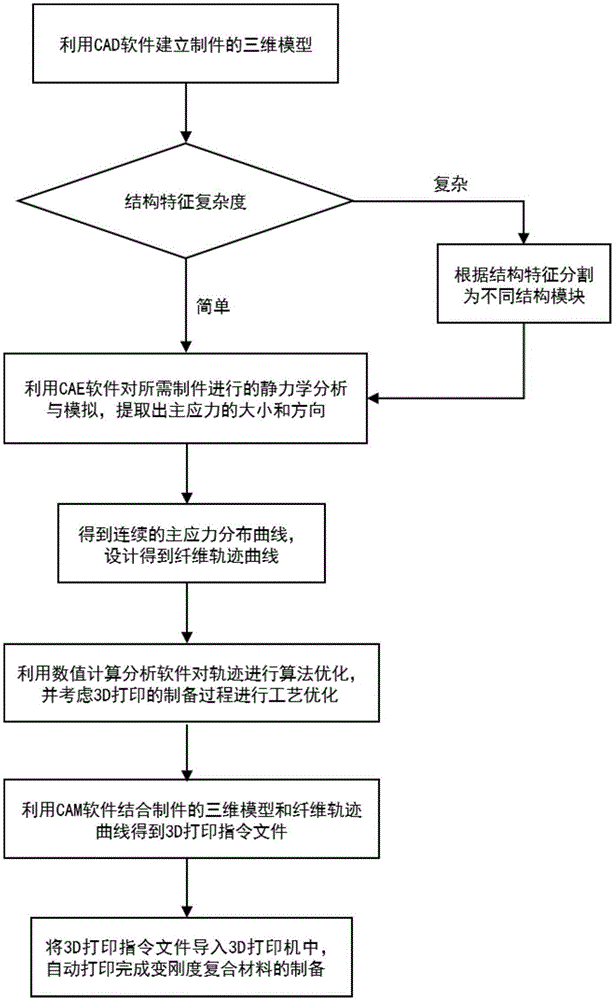
[0030] Reference figure 1 , A method for preparing a functional control structure based on continuous fiber composite 3D printing, including the following steps:
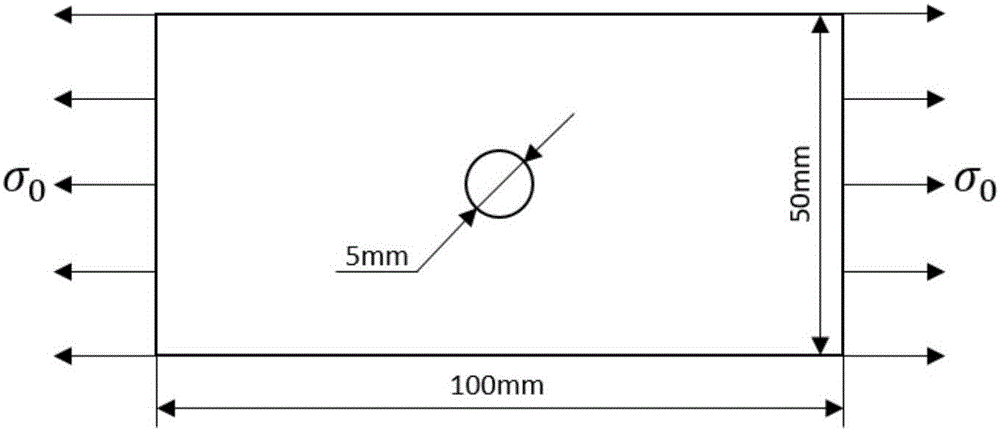
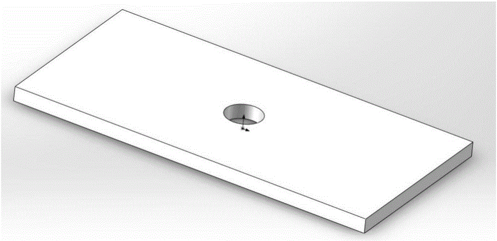
[0031] 1) Build a three-dimensional model: follow figure 2 The size and data of the fiber composite material, using the computer-aided design CAD software Solidworks, according to the shape characteristics of the fiber composite material, establish such as image 3 The three-dimensional model of the part is shown, and the STL file of the part model is derived. Since the structural feature of this embodiment is relatively simple, the whole three-dimensional model is directly selected for the next operation;
[0032] 2) Static analysis and simulation: Import the three-dimensional model into the computer-aided engineering CAE software ABAQUS, perform static analysis on the fiber composite material sample to be prepared, and simulate the actual force of the part under tensile conditions to obtain The distribution characteristics and trends of the principal stress, and extract the main stress concentration area and the magnitude and direction of the main stress of the workpiece;
[0033] 3) Fiber trajectory generation: According to the distribution characteristics of the principal stress size and direction obtained by the static analysis, a continuous principal stress distribution curve is obtained, Figure 4 It is a schematic diagram of the linear fiber trajectory of an ordinary composite material, and there are problems such as stress concentration and weak mechanical properties; the method of the present invention uses the static analysis structure in the previous step to carry out the variable stiffness design of the corresponding concentrated area, and the result is used to describe the fiber trajectory Curve like Figure 5 Shown
[0034] 4) Fiber trajectory optimization: First, use the numerical calculation and analysis software MATLAB to optimize the fiber curve trajectory obtained in the previous step to obtain the optimized trajectory of the part. The optimized algorithms include least squares, cellular automata (CA ) And genetic algorithm and other optimization algorithms; secondly, considering the technological means in 3D printing, optimize and adjust the fiber trajectory, including the parameters of fiber direction angle, fiber placement density, printing scanning distance and printing thickness, to obtain the final fiber trajectory curve;
[0035] 5) Generate part path: Import the 3D model of the part in step 1) into the computer-aided manufacturing CAM software, generate the 3D printing path of the part according to the fiber trajectory curve obtained in step 4), and calculate the printing according to the 3D printing process The final 3D printing instruction file is obtained by the various process parameters at the time;
[0036] 6) Complete 3D printing preparation: Import the 3D printing instruction file generated in step 5) into the 3D printer, select polylactic acid (PLA) as the resin matrix and aramid fiber as the reinforcement material, and complete the transformation according to the path and process parameter information. Preparation of rigid fiber composite materials.

PUM

no PUM

Description & Claims & Application Information

We can also present the details of the Description, Claims and Application information to help users get a comprehensive understanding of the technical details of the patent, such as background art, summary of invention, brief description of drawings, description of embodiments, and other original content. On the other hand, users can also determine the specific scope of protection of the technology through the list of claims; as well as understand the changes in the life cycle of the technology with the presentation of the patent timeline. Login to view more.

Similar technology patents

Grafted modified starch slurry

InactiveCN102050925AImprove mechanical propertiesSave raw materials and energyFibre treatmentButyl methacrylateAmmonium sulfate
Owner:四川海旺科技有限公司

Classification and recommendation of technical efficacy words

  • Strong applicability
  • Improve mechanical properties

Intelligent assisted driving method and system

Owner:CHINA UNIV OF GEOSCIENCES (WUHAN)

Method and device for identifying image definition

ActiveCN105809704AIdentify wellStrong applicabilityImage enhancementImage analysisRegion of interestDistinctness of image
Owner:BEIJING XIAOMI MOBILE SOFTWARE CO LTD

Filtering rod for cigarette and preparing method

InactiveCN101023811AGood filterabilityImprove mechanical propertiesTobacco smoke filtersN-vinyl-pyrrolidone polymer adhesivesPolyesterChemistry
Owner:CHANGCHUN INST OF APPLIED CHEMISTRY - CHINESE ACAD OF SCI
Why Eureka
Try Eureka