A Bypass Valve Realizing Segmented Overflow

A valve and overflow technology, which is applied in the direction of controlling the pressure of lubricant, can solve the problems of lubricating oil pressure fluctuations, long valve strokes, and long valve moving strokes, and achieve small lubricating oil pressure fluctuations, shortened moving strokes, and adjustment accuracy high effect

Active Publication Date: 2015-10-14
AECC SHENYANG ENGINE RES INST
View PDF6 Cites 0 Cited by
  • Summary
  • Abstract
  • Description
  • Claims
  • Application Information

AI Technical Summary

Problems solved by technology

If the oil supply pressure varies in a large range, the moving stroke of the valve will be longer, which will easily cause stagnation, resulting in fluctuations in lubricating oil pressure; secondly, the stroke of the valve is longer, and the machining accuracy of the mating surface of the valve and the shell is required to be high, and the manufacturability is poor

Method used


Image

  • A Bypass Valve Realizing Segmented Overflow
  • A Bypass Valve Realizing Segmented Overflow
  • A Bypass Valve Realizing Segmented Overflow

Examples


Embodiment 1

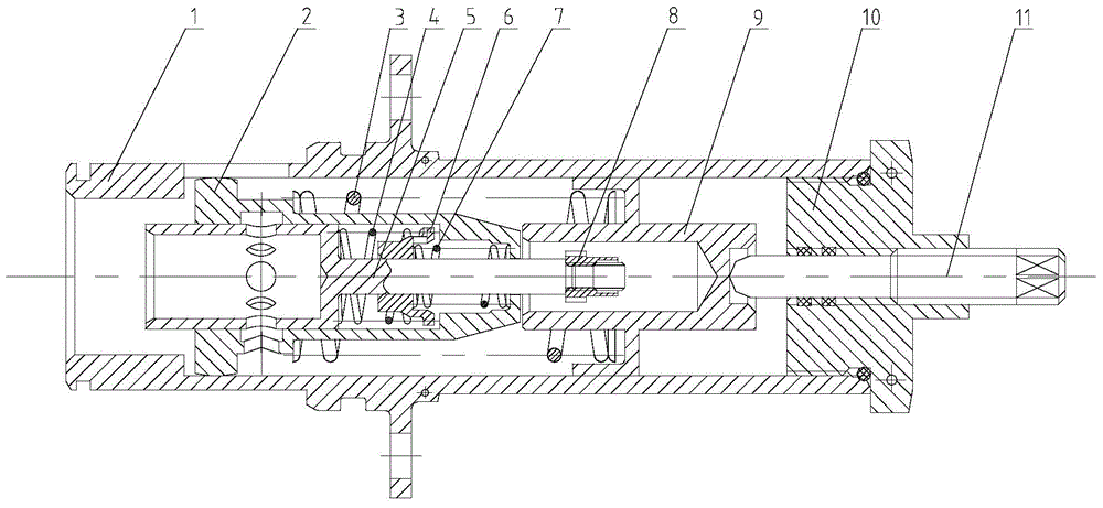
[0016] This embodiment provides a bypass valve for realizing segmental overflow, which is characterized in that: the bypass valve for realizing segmental overflow includes a housing 1, a large valve 2, a first spring 3, a second Spring 4, small valve 5, first positioning block 6, third spring 7, nut 8, second positioning block 9, locking nut 10, adjusting screw 11;

[0017] The casing 1 is connected with the lubricating oil pump group; the large valve 2 compresses the first spring 3 to move in the casing 1; the small valve 5 compresses the second spring 4, pushes the first positioning block 6, and compresses the third spring 7 in the hole of the large valve 2 Internal movement; the nut 8 is connected with the small valve 5 to prevent the small valve 5 from coming out of the large valve 2 when the lubricating oil pressure is low; the adjusting screw 11 is connected with the lock nut 10, and the lock nut 10 is connected with the housing 1, through the adjustment screw The adjust...

Embodiment 2

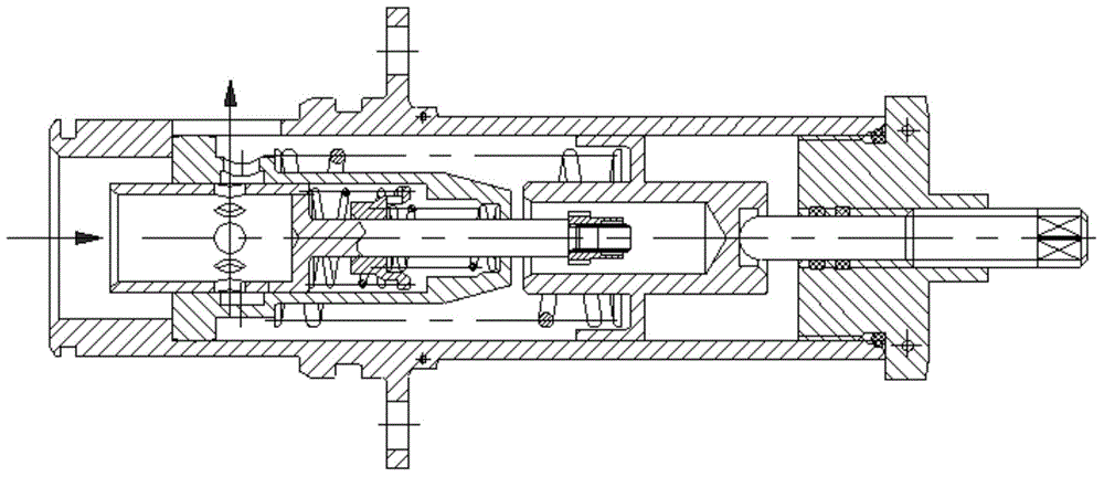
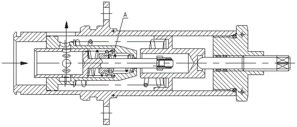
[0021] This embodiment provides a bypass valve for realizing segmental overflow, which is characterized in that: the bypass valve for realizing segmental overflow includes a housing 1, a large valve 2, a first spring 3, a second Spring 4, small valve 5, first positioning block 6, third spring 7, nut 8, second positioning block 9, locking nut 10, adjusting screw 11;

[0022] The housing 1 is connected with the lubricating oil pump group; the large valve 2 compresses the first spring 3 to move in the housing 1; the small valve 5 compresses the second spring 4, pushes the first positioning block 6, and compresses the third spring 7 in the hole of the large valve 2 Internal movement; the nut 8 is connected with the small valve 5 to prevent the small valve 5 from coming out of the large valve 2 when the lubricating oil pressure is low; the adjusting screw 11 is connected with the lock nut 10, and the lock nut 10 is connected with the housing 1, through the adjustment screw The adju...


PUM


Abstract

The invention provides a bypass valve realizing segmented overflow. The bypass valve comprises a casing, a large valve, a first spring, a second spring, a small valve, a first positioning block, a third spring, a screw nut, a second positioning block, a locking screw nut and a regulating screw, wherein the casing is connected with a lubricating oil pump group, the large valve compresses the first spring to move in the casing, the small valve compresses the second spring, pushes the first positioning block and compresses the third spring to move in a large valve hole, the screw nut is connected with the small valve, the small valve is prevented from being disengaged from the large valve when the lubricating pressure is smaller, the regulating screw is connected with the locking screw nut, the locking screw nut is connected with the casing, and through the regulation by the regulating screw, the second positioning block is pushed to move, so the pretightening force of the first spring is regulated. The bypass valve has the advantages that along with the increase of the lubricating oil pressure, the two valves compress the springs to realize the segmented movement, the valve movement stroke is shortened, the clamping stagnation cannot easily occur, the valve regulation precision is high, the overflow is stable, and the lubricating oil pressure fluctuation is small.

Description

technical field [0001] The invention relates to the field of aero-engine lubricating systems, in particular to a bypass valve for realizing segmental overflow. Background technique [0002] At present, the bypass valves of the lubrication system of aero-engines all use a compressed primary spring to adjust the lubricating oil pressure. When the oil supply pressure is greater than the valve opening pressure, the spring is compressed, the valve opens, and the lubricating oil will overflow and return, and the oil supply pressure is kept constant by adjusting the movement of the valve. If the oil supply pressure varies in a large range, the moving stroke of the valve will be longer, which will easily cause stagnation, resulting in fluctuations in lubricating oil pressure; secondly, the stroke of the valve is longer, and the machining accuracy of the mating surface of the valve and the housing is required to be high, and the workmanship is poor. Contents of the invention [00...

Claims


Application Information

Patent Timeline
Patent Type & Authority Patents(China)
IPC IPC(8): F01M1/16
Inventor 苏媛媛毛宏图毛福荣刘晨昊宋冠麟
Owner AECC SHENYANG ENGINE RES INST
Why Eureka
Try Eureka