
Safety device for railway vehicles

a safety device and vehicle technology, applied in buffer cars, railway components, transportation and packaging, etc., can solve the problems of serious consequences, particularly worrisome and dangerous running over, and disastrous consequences of railway vehicles, so as to reduce the negative consequences of collisions or running overs

Inactive Publication Date: 2015-10-06
VALE LIMITED
View PDF11 Cites 2 Cited by
  • Summary
  • Abstract
  • Description
  • Claims
  • Application Information

AI Technical Summary

Benefits of technology

[0007]One of the objectives of this present invention, therefore, is to provide a safety device capable of reducing the negative consequences resulting from collision or running over involving railway vehicles.
[0008]Another objective of this present invention is to provide a safety device capable of reducing the impact from the collision between a railroad car and a pedestrian.BRIEF SUMMARY OF THE INVENTION
[0009]This present invention meets the aforementioned objectives by means of a safety device for railway vehicles consisting of a main impact dampening area and at least one secondary support and resistance area. The safety device is installed on front of the railroad car so that the main impact dampening area dampens the force generated by the collision between the vehicle and a pedestrian.

Problems solved by technology

The accidents involving railway vehicles (i.e. locomotives, wagons) often have serious consequences, since material damage to the equipment until serious injury or death of those involved.
If the prevention of this kind of accident fails the results are disastrous.
Considering the most common railway accidents, running over is particularly worrisome and dangerous.
The dimensions and weight of the railroad car cause a fatality as a consequence of this type of impact.
Other equally tragic, yet common injuries include serious injuries such as mutilation or generalized fractures.
Even if impact is only partial, the shock of collision between railroad cars and people results in consequences as disastrous as those mentioned above.

Method used


Image

  • Safety device for railway vehicles
  • Safety device for railway vehicles
  • Safety device for railway vehicles

Examples


Embodiment Construction

[0030]The present invention shall be further detailed based on the execution example depicted in the drawings.

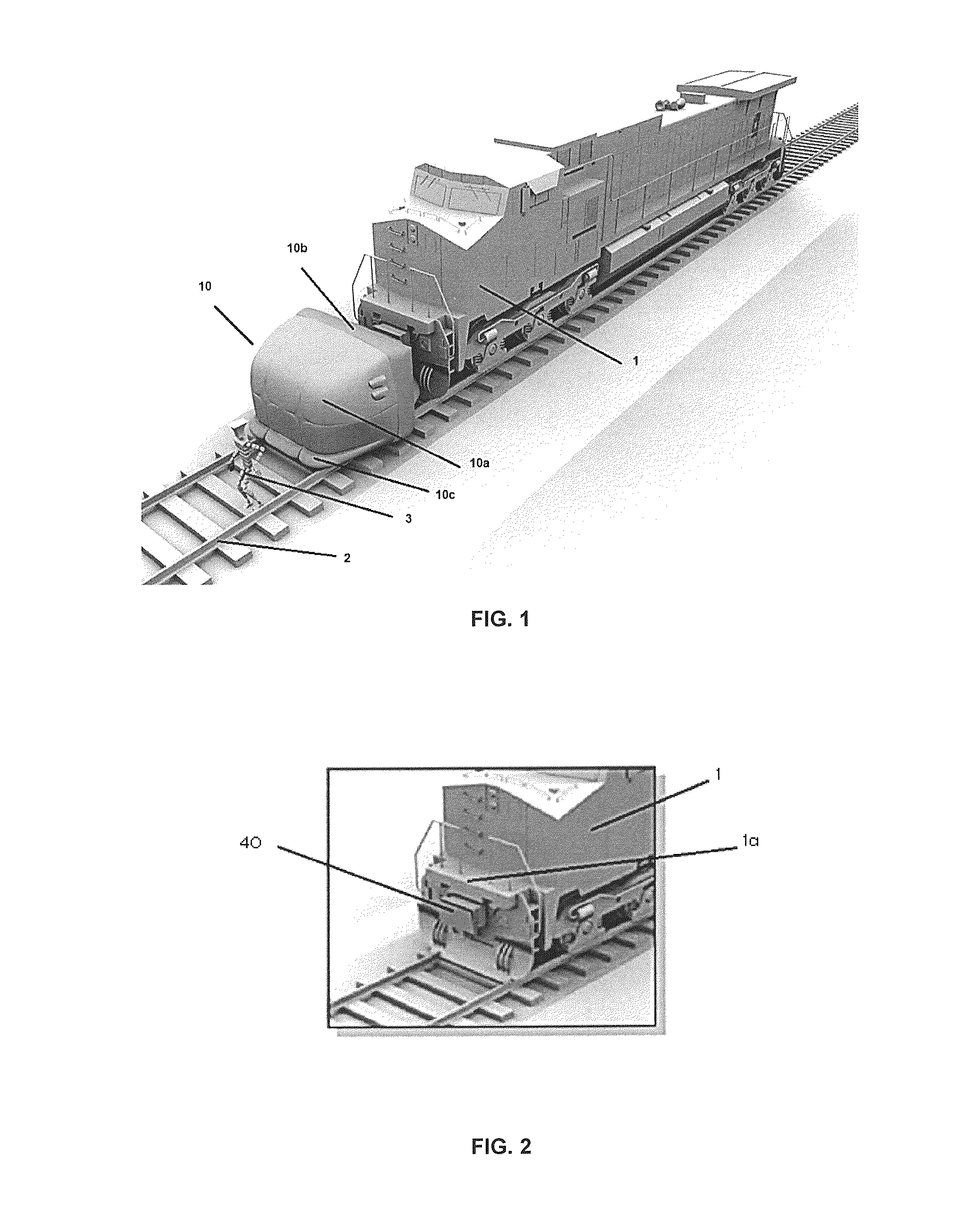
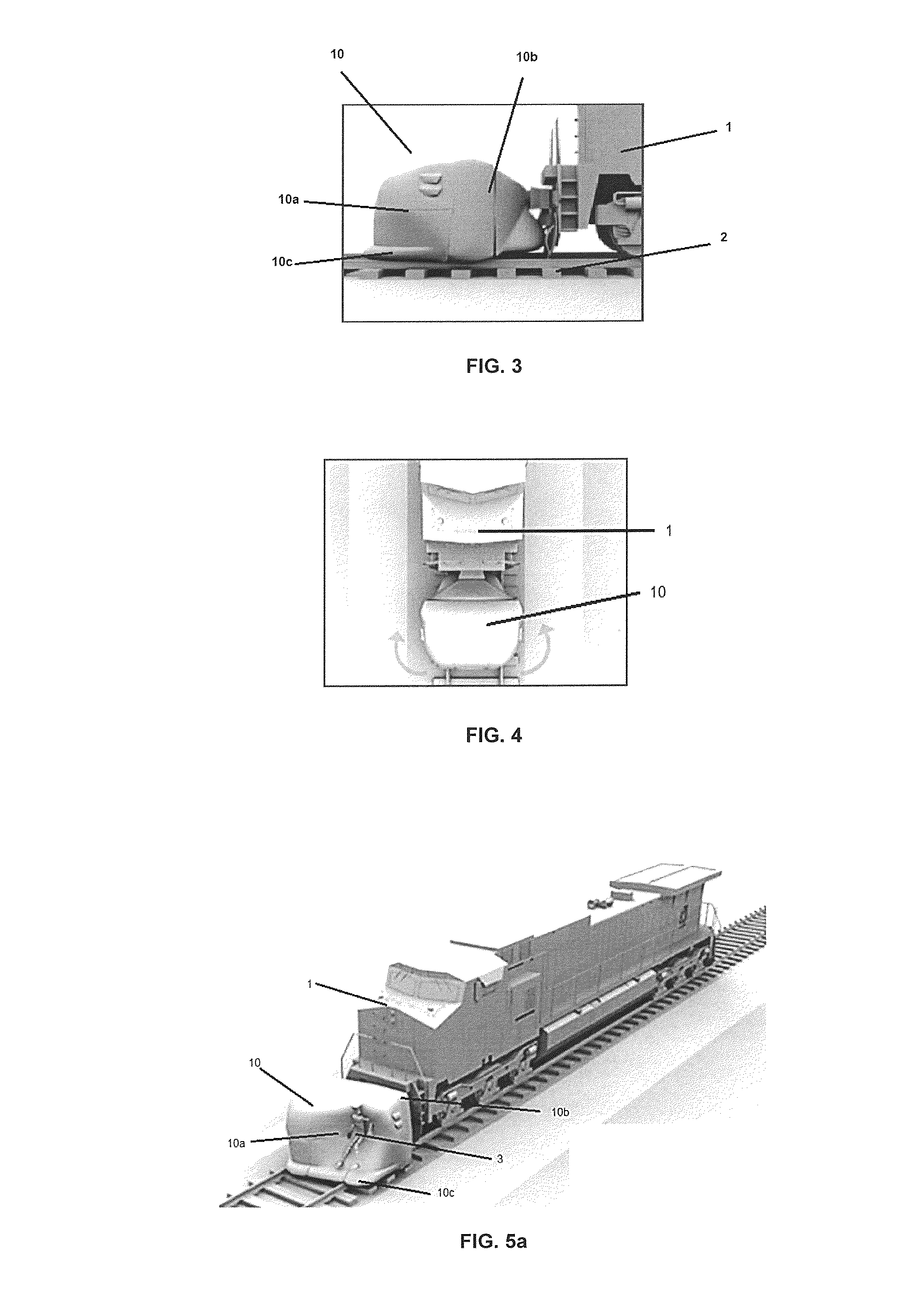
[0031]FIGS. 1-5 show a preferred embodiment of the safety device.

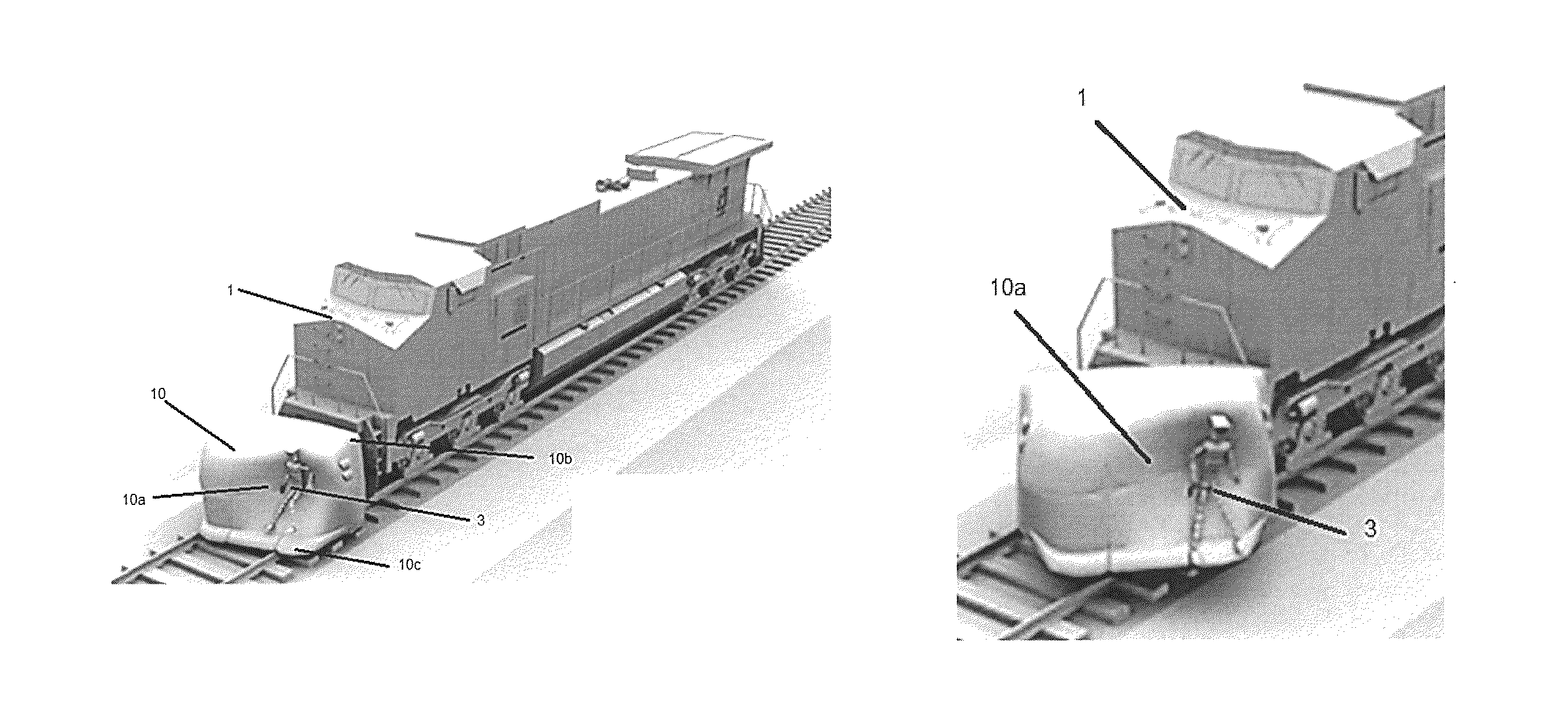
[0032]FIG. 1 shows a railroad car (locomotive) 1 moving along the tracks 2. A pedestrian 3 is shown on the tracks at risk of being struck, and the safety device 10 is shown after being actuated / inflated.

[0033]As shown in the figures, the safety device is intended to be installed on the vehicle's front end 1.

[0034]In the preferred embodiment, the device 10 consists of an inflatable body with a main impact dampening area 10a and two secondary resistance and support areas 10b and 10c.

[0035]The main impact dampening area 10a consists of an inflatable bag whose pressure is less than that of the secondary resistance and support areas 10b and 10c. Therefore, impact dampening area 10a is suitable for dampening the impact with pedestrian 3 at the time of collision, whereas areas 10b and 10c provide the needed resistanc...


PUM


Abstract

A safety device for railway vehicles is provided, more specifically a safety device that reduces the negative consequences resulting from collisions or pedestrian accidents involving railway vehicles. As such, the railway vehicle safety device consists of a main impact dampening area and at least one secondary support and resistance area, with the safety device being installed on the railway vehicle's front end, so that the main impact dampening area dampens the force of the impact caused by a collision between the vehicle and a pedestrian.

Description

CROSS-REFERENCE TO RELATED APPLICATIONS[0001]This application claims priority to U.S. Provisional Patent Application No. 61 / 668,745, filed Jul. 6, 2012. The disclosure of the prior application is hereby incorporated in its entirety by reference.THE FIELD OF THE INVENTION[0002]The present invention refers to a safety device for railway vehicles, more specifically to a safety device that reduces the negative consequences resulting from collisions or pedestrian accidents involving railway vehicles.BACKGROUND[0003]The accidents involving railway vehicles (i.e. locomotives, wagons) often have serious consequences, since material damage to the equipment until serious injury or death of those involved.[0004]Generally, the efforts to prevent railway accidents have been focused on their prevention: collision sensors, alarms, planning escape routes, and other types of preventive methods or devices. If the prevention of this kind of accident fails the results are disastrous.[0005]Considering t...

Claims


Application Information

Patent Timeline
Patent Type & Authority Patents(United States)
IPC IPC(8): B61D15/06B61F19/06
CPCB61D15/06B61F19/06
Inventor SOMENSI, CAUE STOCCHI
Owner VALE LIMITED
Learn More