Mounting structure of buffer member for fuel tank

a technology of buffer member and mounting structure, which is applied in the direction of mechanical equipment, couplings, transportation and packaging, etc., can solve the problems of reducing the adhesion strength, high accuracy is required at the time of assembly, and the inability to obtain stable adhesion strength, etc., to achieve easy and stable mounting to the fuel tank, improve the connection strength between the clip and the buffer member, and improve the adhesive strength

Active Publication Date: 2015-10-13
YACHIYO IND CO LTD
View PDF13 Cites 4 Cited by
  • Summary
  • Abstract
  • Description
  • Claims
  • Application Information

AI Technical Summary

Benefits of technology

[0009]According to the above structure, since the first convex portion is pushed into the second concave portion and the second convex portion is pushed into the first concave portion when an external force is applied to the buffer member, the cushion feature can be improved. Also, since the leg portion is engaged with the recess, degradation of adhesive, etc. does not affect a connection strength and degradation in a connection strength caused by age degradation can be prevented. Also, the buffer member can be mounted to the fuel tank easily and stably by only pushing the leg portion of the buffer member into the recess.
[0011]According to the above structure, since the first convex portion is pushed into the second concave portion and the second convex portion is pushed into the first concave portion when an external force is applied to the buffer member, the cushion feature can be improved. Also, since the buffer member is mounted to the fuel tank via the clip, degradation of adhesive, etc. does not affect a connection strength and degradation in a connection strength caused by age degradation can be prevented. Also, since the removal proof edge is formed on the head portion of the clip, a connection strength between the clip and the buffer member can be improved. Also, the buffer member can be mounted to the fuel tank easily and stably by only pushing the buffer member and the clip into the recess of the fuel tank.
[0012]Also, a projection portion which projects toward a center of an opening of the recess is preferably formed in the recess. According to the above structure, a connection strength between the projection portion and the leg portion can be improved.
[0013]Also, the removal proof edge preferably comprises: an inclined surface which inclines toward the substrate portion as it becomes apart from a center axis of the head portion; and a barb surface which is extended from the outer surface of the head portion to a tip of the inclined surface and serves as a barb. According to the above structure, the buffer member can be engaged with the clip easily, and the buffer member can hardly be removed from the clip by virtue of the barb surface once the engagement is established.
[0014]Also, a salient which projects toward a center of an opening of the hole is preferably formed in the hole. According to the above structure, a connection strength between the hole and the head portion of the clip can be improved.

Problems solved by technology

However, in adhesion by the adhesive or the double-faced tape, there arises a problem that a plasticizer contained in the buffer member is drawn to an adhesive interface as time passes and an adhesive strength is lowered.
Also, since the adhesive strength of the buffer member depends on a strength of pressure to press the buffer member, a stable adhesive strength can not be obtained.
Also, since the buffer member can not be removed easily once it is adhered, high accuracy is required at the time of assembling.
For this reason, there arises a problem that a large burden is imposed on a worker.
Also, since a buffer member of the prior art shows an approximately tabular appearance, it has a poor cushion feature.

Method used


Image

  • Mounting structure of buffer member for fuel tank
  • Mounting structure of buffer member for fuel tank
  • Mounting structure of buffer member for fuel tank

Examples


first embodiment

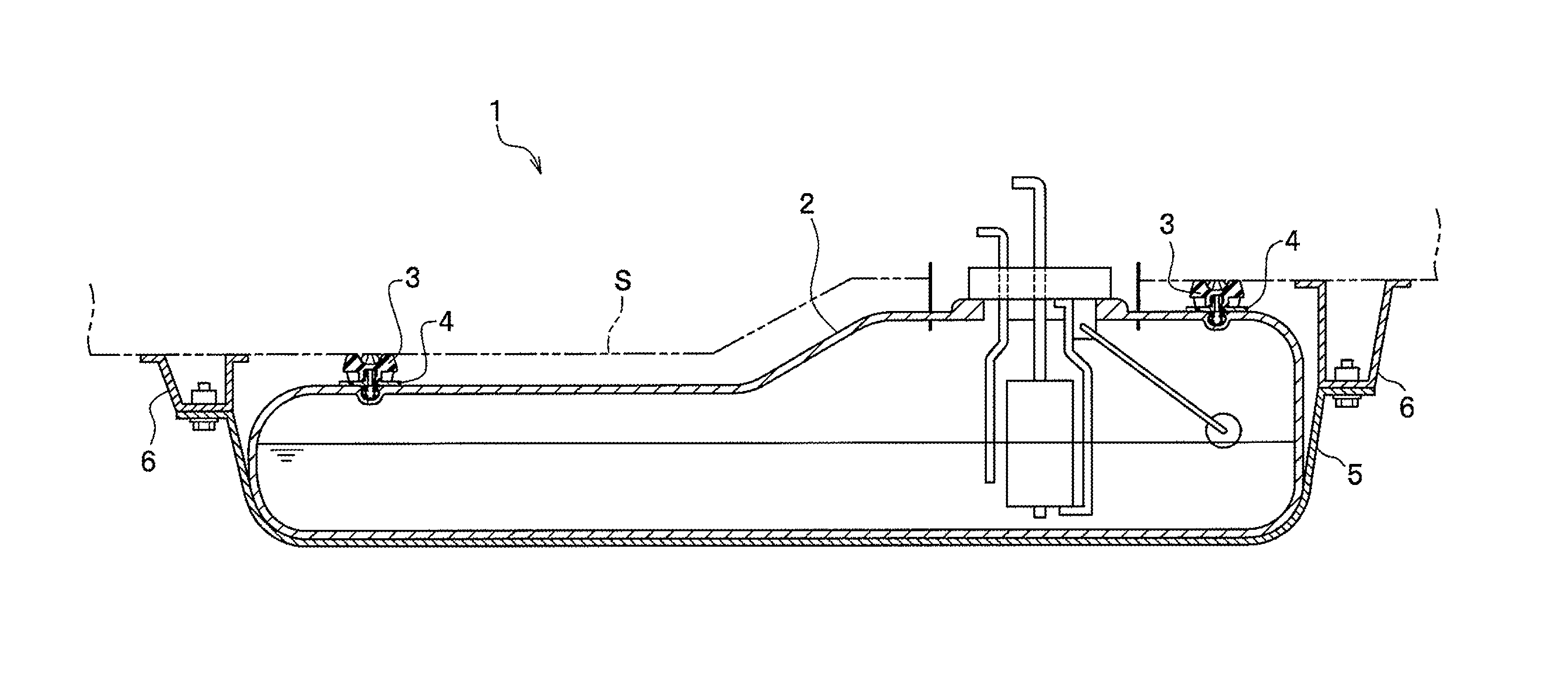
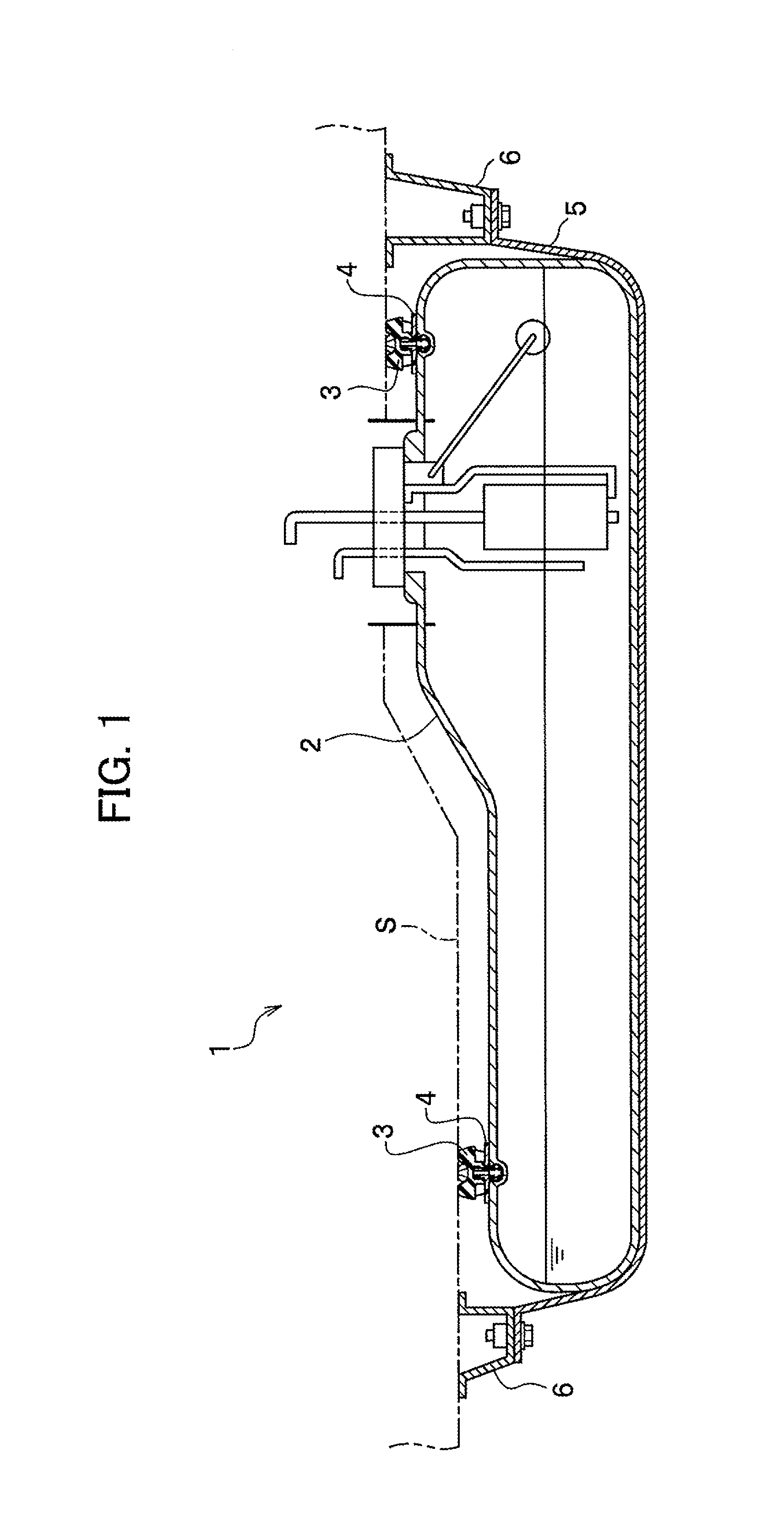
[0024]With reference to drawings, a first embodiment of the present invention will be explained in detail. As shown in FIG. 1, a mounting structure 1 according to this embodiment relates to a mounting structure of a buffer member 3 installed between a fuel tank 2 and a vehicle body S of a vehicle. The mounting structure 1 mainly comprises: the fuel tank 2; the buffer member 3; and a clip 4.

[0025]The fuel tank 2 is a hollow container made of resin or metal for storing fuel, and is fixed to a bottom (a floor panel) of the vehicle body S. In this embodiment, a bottom of the fuel tank 2 is supported by a U-shaped tank band 5, and both ends of the tank band 5 is fixed to the vehicle body S via brackets 6, 6.

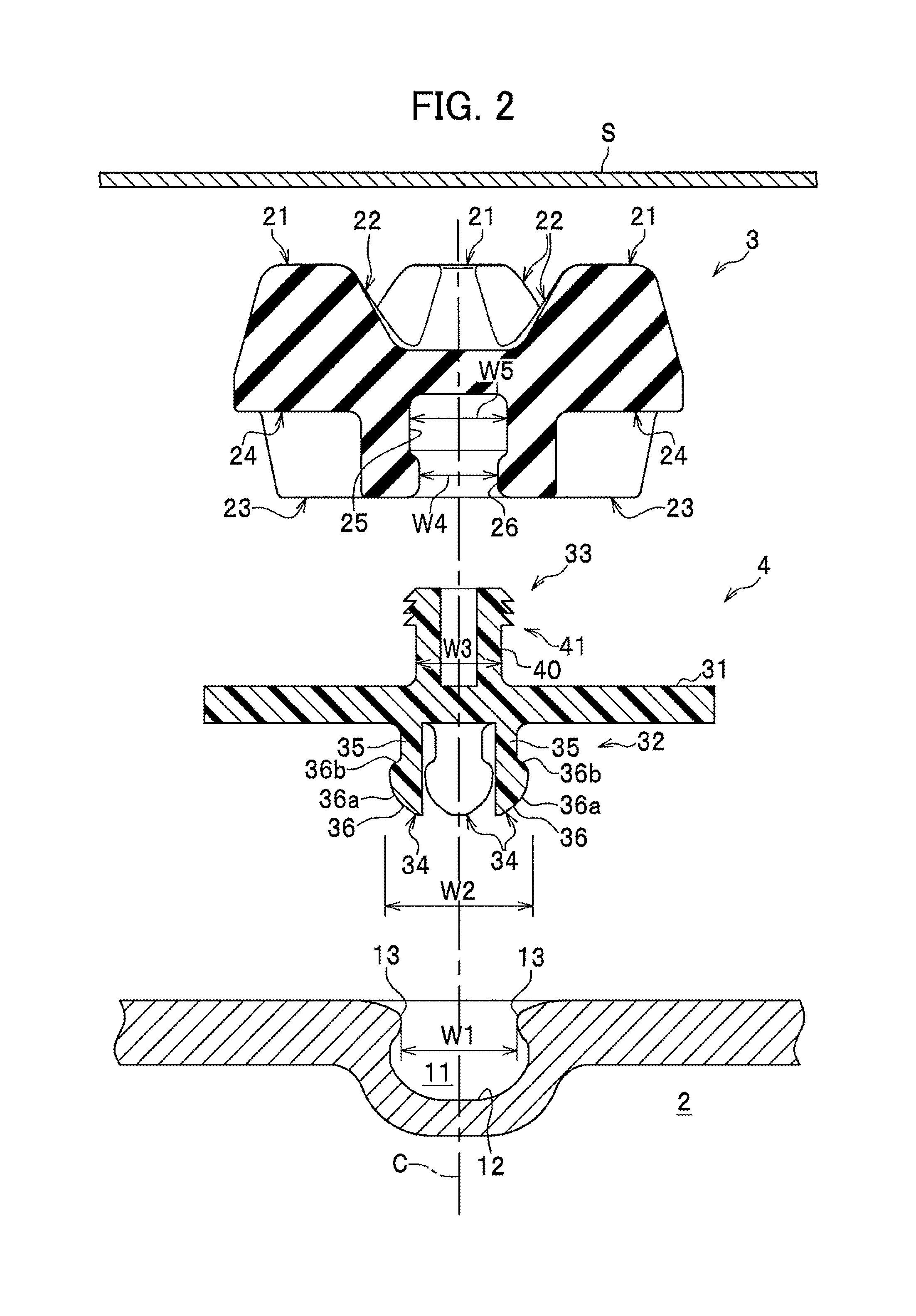
[0026]As shown in FIGS. 2 and 4, a recess 11 is formed on a surface of the fuel tank 2. A leg portion 32 of the clip 4 is engaged with the recess 11. In this embodiment, the recess 11 is formed on the surface opposite to the vehicle body S of the fuel tank 2. The recess 11 has a round...

second embodiment

[0052]Next, a second embodiment of the present invention will be explained. As shown in FIG. 7, a mounting structure 1A according to the second embodiment mainly comprises: a fuel tank 2; and a buffer member 3A. The mounting structure 1A according to the second embodiment differs from that according to the first embodiment in that the mounting structure 1A does not comprises a clip. With respect to the fuel tank 2, since it is the same as that of the first embodiment, detailed explanation will be omitted.

[0053]As shown in FIG. 7, the buffer member 3A is made of a rubber, and installed between the fuel tank 2 and the vehicle body S. The buffer member 3A has a body portion 61, and a leg portion 71 which is extended from the body portion 61 toward a recess 11. In this embodiment, the buffer member 3A is integrally molded.

[0054]As shown in FIGS. 7 and 8, the body portion 61 is configured to be round in a plan view, and has a first convex portion 21, a first concave portion 22, a second ...


PUM


Abstract

A mounting structure wherein a buffer member has a body portion, and a leg portion which is extended from the body portion and engaged with a recess, wherein the body portion has a plurality of first convex portions which are arranged around a center axis of the body portion at regular intervals and abut against a vehicle body, a plurality of first concave portions each of which is formed between the adjacent first convex portions, a plurality of second convex portions which are arranged around the center axis of the body portion 61 at regular intervals and abut the fuel tank, and a plurality of second concave portions each of which is formed between the adjacent second convex portions, and wherein the first convex portion is formed corresponding to the second concave portion, and the second convex portion is formed corresponding to the first concave portion, is provided.

Description

CROSS REFERENCE TO RELATED APPLICATION[0001]The present application claims benefit of the filing date of Japanese Patent Application No. 2011-043575 filed on Mar. 1, 2011 which is incorporated herein by reference.BACKGROUND OF THE INVENTION[0002]1. Field of the Invention[0003]The present invention relates to a mounting structure of a buffer member installed between a fuel tank for a vehicle and a vehicle body.[0004]2. Description of the Related Art[0005]Conventionally, a technique for installing a buffer member such as a rubber, etc. between a fuel tank for a vehicle and a floor panel of a vehicle body has been well known. By installing the buffer member between the fuel tank and the floor panel, the fuel tank is prevented from striking against the floor panel, and vibration and noise caused by ruffles of fuel in the fuel tank, etc. is prevented from being transmitted to the vehicle body. For example, JP 05-089060 Y discloses that an adhesive layer is provided between a fuel tank an...

Claims


Application Information

Patent Timeline
Patent Type & Authority Patents(United States)
IPC IPC(8): B60K15/067F16F1/376B60K15/03
CPCB60K15/067F16F1/376B60K2015/03032B60K2015/03039Y10T403/45B60K2015/03052B60K2015/03059B60K2015/03065F16F2230/0005B60K2015/03046
Inventor INABA, RYUTAROSEKO, MITSUHIRO
Owner YACHIYO IND CO LTD
Why Eureka
Try Eureka