
Rotation pointed antenna for fixed wireless wide area networks

a fixed wireless wide area network and antenna technology, applied in the field of wireless communication systems, can solve the problems of limited wireless voice and data services, inability to transmit power or receive enough signal strength to communicate in certain areas, and affect the coverage and capacity of wireless networks

Active Publication Date: 2015-10-13
DIRECTV LLC
View PDF23 Cites 5 Cited by
  • Summary
  • Abstract
  • Description
  • Claims
  • Application Information

AI Technical Summary

Benefits of technology

[0020]Further, there may be a mechanism that prevents over-rotation of the antenna assembly, as well as a link quality indicator, provisioned on the housing or a base for the housing, that provides a visual status of wireless link quality.

Problems solved by technology

Wireless voice and data services, however, are limited by the ability of the wireless network to communicate where its signals may be blocked or otherwise where there is insufficient signal strength.
For example, mobile devices typically have antennas with limited gain, and therefore the antenna on the mobile device cannot transmit enough power or receive enough signal strength to communicate in certain areas.
Other limitations on wireless networks include urban environments with their resultant multi-path interference, rural environments with their lack of network infrastructure, and coverage inside buildings with their signal attenuation that may prevent reception or degrade signals in the wireless network, impacting both coverage and capacity of the wireless network.
In particular, limitations of available spectrum for 4G services force the reuse of allocated spectrum, resulting in greater interference levels, thereby affecting the provision of 4G service.

Method used


Image

  • Rotation pointed antenna for fixed wireless wide area networks
  • Rotation pointed antenna for fixed wireless wide area networks
  • Rotation pointed antenna for fixed wireless wide area networks

Examples


first embodiment

[0059]FIG. 5(a) is a cross-section side view of the cantenna 16, according to a As shown, the cantenna 16 is a closed cylinder comprised of the housing 64 mounted on the base.

[0060]66, the antenna assembly is rotatably mounted within the closed cylinder, and the motor 68 mechanically rotates the antenna assembly about a central axis of the closed cylinder.

[0061]The housing 64 is typically transparent to the frequencies of interest being transmitted and received by the antenna 40. In one embodiment, these frequencies are in ranges of the 700, 1900, or 1700 / 2100 MHz, but can be of any frequency range without departing from the scope of the present specification.

[0062]The base 66 is a structural element that supports the other elements of the cantenna 16. Preferably, the base 66 engages with the housing 64 in a manner that encloses all of other components of the cantenna 16 in a weather-proof package

[0063]As shown in FIG. 5(a), the antenna assembly may be comprised of two PCBs 72 and ...

second embodiment

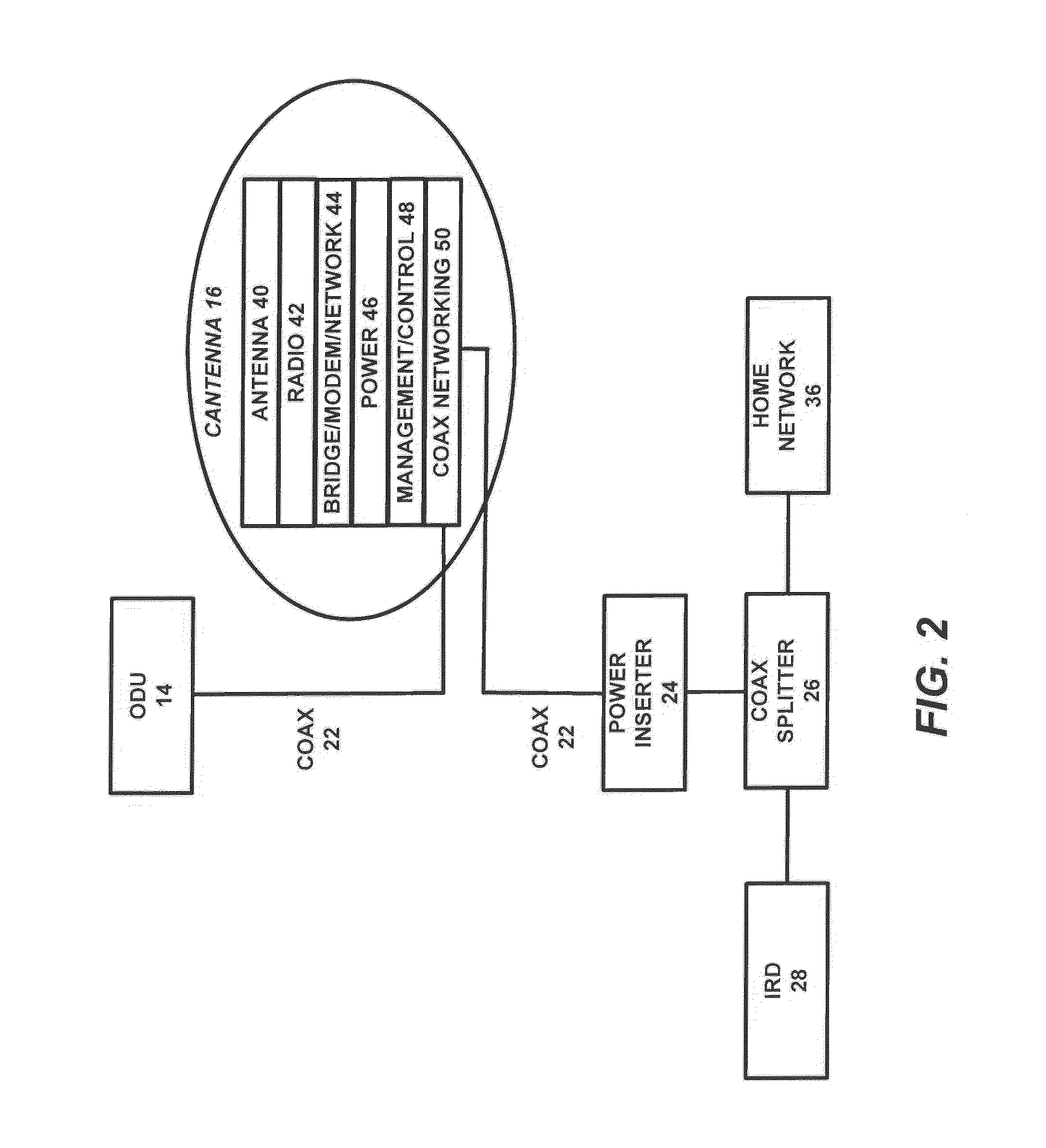
[0074]FIG. 5(b) is a cross-section side view of the cantenna 16, according to a In this embodiment, the modules 42, 44, 46, 48 and 50 are implemented on a single PCB 74 that is mounted on and fixed to the base 66 of the housing 64, wherein only the PCB 72 implementing the antenna 40 is rotated. Similarly, the motor 68 is also mounted on and fixed to the base 66.

[0075]FIG. 5(c) is a cross-section front view of the cantenna 16, according to the second embodiment. A similar view would exist for the first embodiment, except that the PCB 74 implementing the modules 42, 44, 46, 48, 50 would be hidden, because it would be mounted on the opposite side from the PCB 72 implementing the antenna 40, rather than on the base 66.

[0076]FIG. 5(d) is a cross-section top view of the cantenna 16, according to the first Embodiment. The semicircular arrows within the housing 64, on opposite sides of the rotating antenna assembly comprised of the plate 70a, PCB 72, and PCB 74, are intended to indicate on...


PUM


Abstract

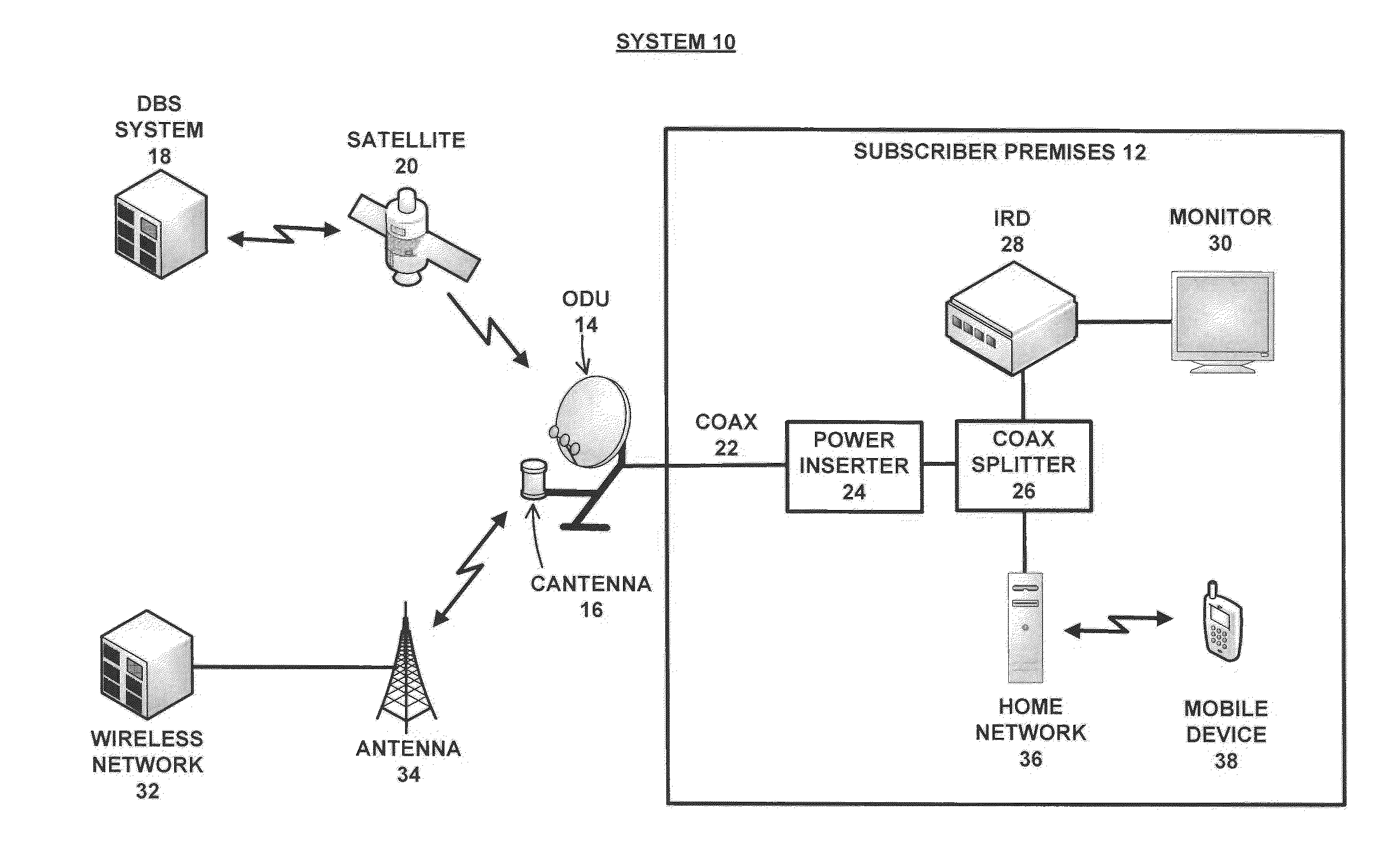
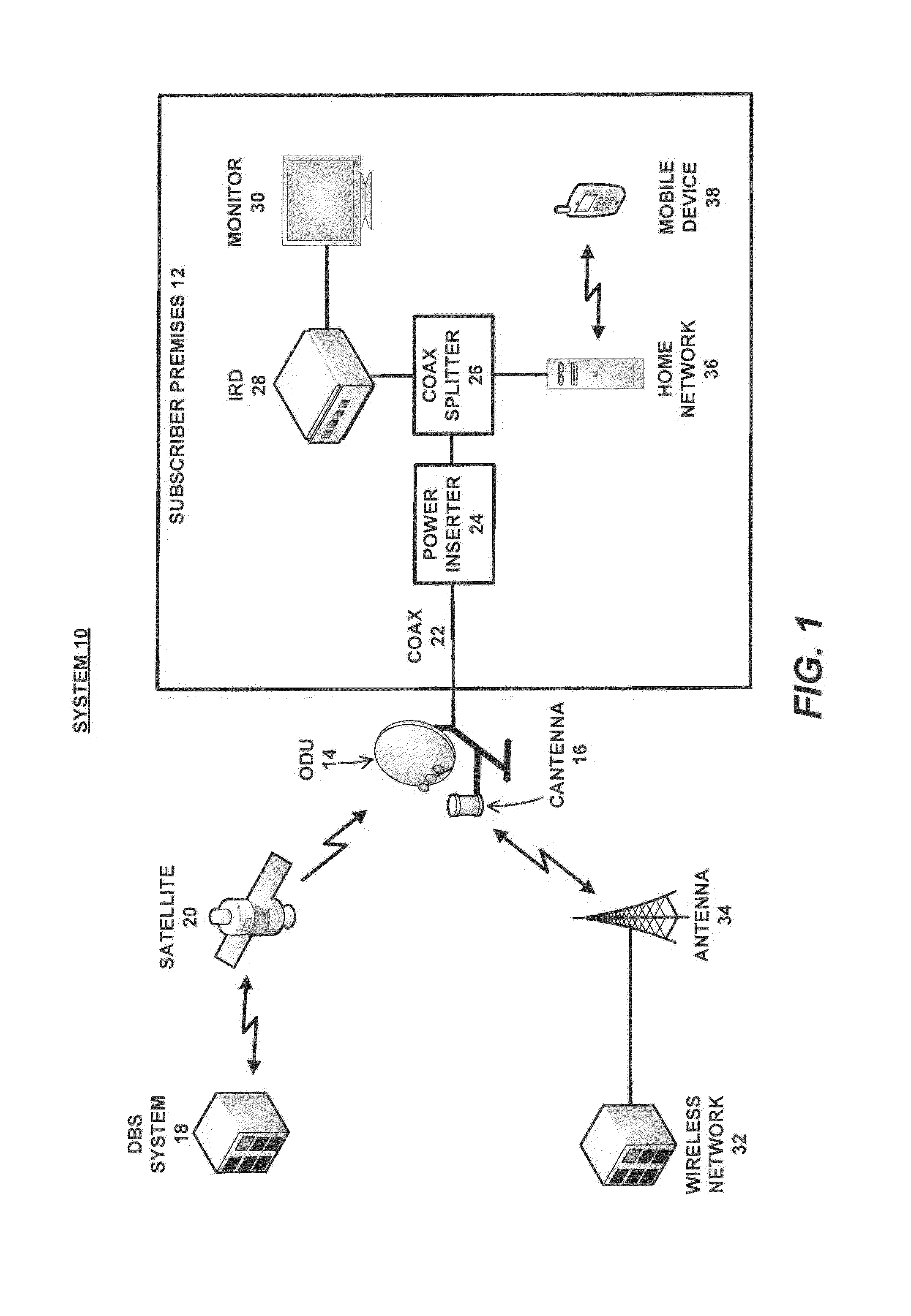
An apparatus and method for combining signals received from a direct broadcast satellite system with signals received from a wireless network, includes a satellite antenna for receiving the signals from the direct broadcast satellite system; and a wireless network antenna, co-located with the satellite antenna, for receiving the signals from the wireless network. The wireless network antenna includes an antenna assembly that is rotated by a controller based on characteristics of the signals received from the wireless network. The controller energizes and de-energizes a motor to mechanically rotate the antenna assembly to properly align the wireless network antenna to communicate with the wireless network. The wireless network antenna comprises a closed cylinder, wherein the antenna assembly is rotatably mounted within the closed cylinder, such that, upon command from the controller, the motor engages the antenna assembly to mechanically rotate the antenna about a central axis of the closed cylinder.

Description

CROSS-REFERENCE TO RELATED APPLICATIONS[0001]This application is a continuation-in-part of the following co-pending and commonly-assigned applications:[0002]U.S. Utility application Ser. No. 12 / 797,412, filed on Jun. 9, 2010, by John L. Norin, entitled “OMNIDIRECTIONAL SWITCHABLE BROADBAND WIRELESS ANTENNA SYSTEM,” which application claims the benefit under 35 U.S.C. §119(e) of U.S. Provisional Application Ser. No. 61 / 185,552, filed on Jun. 9, 2009; and[0003]U.S. Utility application Ser. No. 12 / 797,570, filed on Jun. 9, 2010, by John L. Norin, entitled “INTEGRATED SATELLITE-TV BROADBAND WIRELESS SYSTEM,” which application claims the benefit under 35 U.S.C. §119(e) of U.S. Provisional Application Ser. No. 61 / 185,546, filed Jun. 9, 2009;[0004]all of which applications are incorporated by reference herein in their entirety.BACKGROUND[0005]1. Technical Field[0006]The present specification relates generally to wireless communications systems, and in particular to a directional and steera...

Claims


Application Information

Patent Timeline
Patent Type & Authority Patents(United States)
IPC IPC(8): H04H40/90H01Q1/12H04N7/20H04N7/10H04N21/61H04N21/414H01Q19/12H04B7/185H04N21/442H01Q3/04H01Q1/42
CPCH04B7/1851H01Q1/1228H01Q3/04H01Q19/12H04N7/106H04N21/41407H04N21/44209H04N21/6131H04N21/6143H04N7/20H01Q1/42H04B7/18528H04B7/18597Y02D30/70H01Q3/06
Inventor NORIN, JOHN L.POPOLI, ROBERT F.SHAH, DIPAK M.
Owner DIRECTV LLC
Learn More