Removable seat for a motor vehicle

a technology for motor vehicles and seats, applied in vehicle parts, vehicle arrangements, dismountable/non-dismountable seats, etc., can solve the problem of difficult to move seats from one position to another,

Active Publication Date: 2018-03-20
HONDA MOTOR CO LTD
View PDF31 Cites 12 Cited by
  • Summary
  • Abstract
  • Description
  • Claims
  • Application Information

AI Technical Summary

Benefits of technology

[0005]A rail and carrier system for a seat for a motor vehicle includes a first lower rail fixedly attached to and positioned laterally along a floor of the motor vehicle, a first upper rail nested with and laterally slidable within the first lower rail, a second lower rail positioned laterally along the floor of the motor vehicle parallel to the first lower rail and longitudinally rearward of the first lower rail, a second upper rail nested with and laterally slidable within the second lower rail, first and second cross brackets laterally spaced apart and arranged perpendicular to the first and second upper rails, the first and second cross brackets being connected to the first and second upper rails, a cover connected to and extending between the first and second cross brackets, a first front striker attached to a top of a longitudinally forward portion of the first cross bracket, a second front striker attached to a top of a longitudinally forward portion of the second cross bracket, and a first rear striker attached to a top of a longitudinally rearward portion of the first cross bracket, a second rear striker attached to a top of a longitudinally rearward portion of the second cross bracket. The first and second front strikers and first and second rear strikers extend upward through openings in the cover. The seat further includes a first hook fastener for removably attaching the seat to the first front striker, the first hook fastener being rotatable about a lateral axis through the first and second front strikers, a second hook fastener for removably attaching the seat to the second front striker, the second hook fastener being rotatable about the lateral axis through the first and second front strikers, a first hook and lock fastener for removably attaching the seat to the first rear striker, a second hook and lock fastener for removably attaching the seat to the second rear striker, and a bar extending between the first hook fastener and the second hook fastener, the bar being parallel to the lateral axis, the bar contacting the cover to prevent further rotation when the seat is rotated about the lateral axis to prevent over-rotation of the seat.

Problems solved by technology

Moving a seat from one position to another often was difficult, particularly given the weight of the seat and the need to move or remove caps or carpeting.

Method used


Image

  • Removable seat for a motor vehicle
  • Removable seat for a motor vehicle
  • Removable seat for a motor vehicle

Examples


Embodiment Construction

[0068]Embodiments are described with reference to the figures in which like reference numbers indicate identical or functionally similar elements. Also in the figures, the left most digits of each reference number corresponds to the figure in which the reference number is first used.

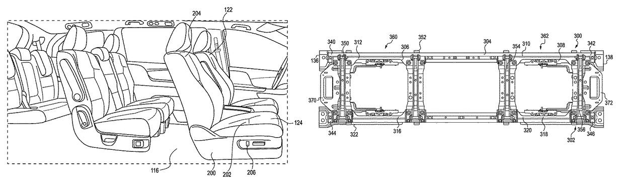
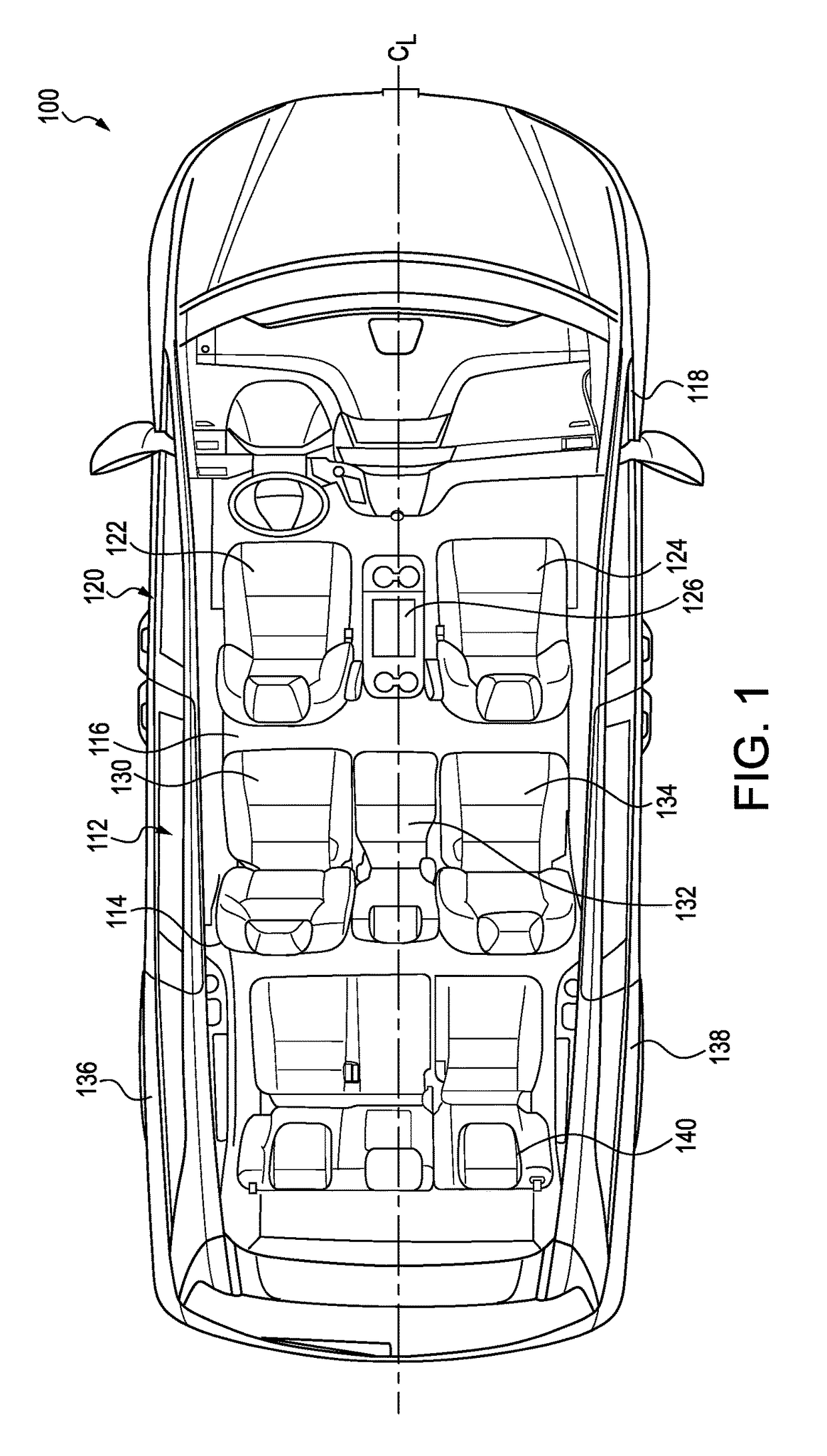
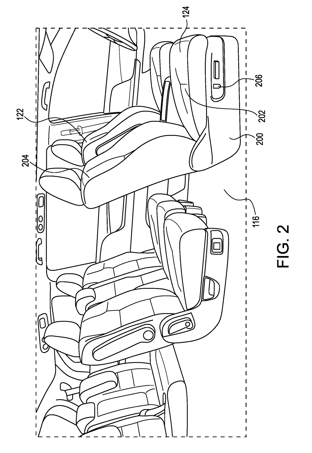
[0069]As illustrated in FIGS. 1-2, the embodiments described herein are directed to a second row seat system 112 for a motor vehicle 100. In the embodiments illustrated in the FIGS. 1-2, the motor vehicle 100 is a minivan, although any other type of vehicle with removable seats 114 may include embodiments of the second row seat system 112.

[0070]As illustrated in FIGS. 1-2, the motor vehicle 100 has a floor 116 that is supported by a body 118. As also shown, there is a front row of seats 120. Shown in FIG. 1 are two individual seats 122, 124, with a folding tray 126 that may lower to the side of the passenger seat 124 to create a walkway to the rear of the motor vehicle 100. The bases 200 of the two front...


PUM


Abstract

A removable seat for a motor vehicle includes two hook fasteners for removably attaching the seat to front strikers that are rotatable about a lateral axis through the front strikers. A bar extends between the first hook fastener and the second hook fastener that is parallel to the lateral axis. The bar contacts the cover to prevent further rotation when the seat is rotated about the lateral axis to prevent over-rotation of the seat.

Description

[0001]The embodiments disclosed a related to the field of removable seats for a motor vehicle.BACKGROUND[0002]Motor vehicles such as minivans often include three rows of seats. In a minivan, the third row of seats often folds to form a flat floor, but there is no room to stow second row seats when the minivan needs to haul cargo. Therefore, second row seats of a minivan are often removable from the motor vehicle.[0003]In addition to the functional desire to remove the seats, there is also a desire to provide multiple seat configurations for increased user functionality. For instance, a center seat may be removed to provide a center aisle in the vehicle to increase access to the third row of seats. Additionally, the two outer seats have been movable from one position to another by selecting different strikers to which the seat may be attached. Typically, unused strikers are covered by caps or carpeting. Moving a seat from one position to another often was difficult, particularly give...

Claims


Application Information

Patent Timeline
Patent Type & Authority Patents(United States)
IPC IPC(8): B60N2/00B60N3/00B60N2/01B60N2/16B60N2/20B60N2/02B60N2/07B60N2/30B60N2/06B60N2/015
CPCB60N2/015B60N2/01B60N2/0228B60N2/06B60N2/065B60N3/002B60N2/0715B60N2/0725B60N2/16B60N2/20B60N2/30B60N2/072B60N2/688B60N3/06B60N2/01583B60N2/062B60N2/0825B60N2/0843B60N2002/0055
Inventor SUPERNAVAGE, PETER AISHIKAWASCHEURER, II, JEFFREY H
Owner HONDA MOTOR CO LTD
Why Eureka
Try Eureka