Cable dispenser

a dispenser and cable technology, applied in the field of electric cables, can solve the problems of cable falling off the spool, cable getting tangled on the axel, cable not de-reeling smoothly, etc., and achieve the effect of convenient loading and easy manufactur

Inactive Publication Date: 2011-06-16
NEXANS
View PDF9 Cites 12 Cited by
  • Summary
  • Abstract
  • Description
  • Claims
  • Application Information

AI Technical Summary

Benefits of technology

[0010]The present arrangement overcomes the drawbacks associated with payoff of both spooled and non-spooled (shrink-wrapped) cable, such as coiled electrical cables, by providing a payoff that is enclosed so that the cable will not jump over the flanges of the spool. The payoff arrangement is lightweight and sturdy and is both easy to manufacture and easy to load, while remaining stable under the heavy weight and forces applied while unwinding the cable.

Problems solved by technology

Sometimes when the cable is pulled quickly, the spool continues to turn when the pull is done and the cable will jump off the spool and get tangled on the axel.
Moreover, the spool may wander on the axel which further complicates installation.
For example, the spool has to be placed more or less perpendicular to the pull or the cable will not de-reel smoothly.
Thus, the installer has to continually intervene to fix the payoff and cable during the pull.
Because the diameter of typical shrink wrapped cable spools are bigger (e.g. to make the shrink wrap package more stable on the skid for shipping reasons), it spins more readily but continues to rotate after the installer stops pulling, then the cable jumps over the flange holder onto the axel, or on other occasions just unravels on the holder and cause tangles that are worse than the tangles from spools.
Also, if the cable is pulled off with a sharp fleeting angle from such a device, the cable jumps off the holder more easily.
However, such a device is difficult to load the cable onto, and thus is time consuming to operate.
Additionally, such a device still suffers from the same over-rotation problem described above.
Likewise, this device is complex and heavy and thus is expensive and difficult to maneuver on job sites.

Method used


Image

  • Cable dispenser
  • Cable dispenser
  • Cable dispenser

Examples


Embodiment Construction

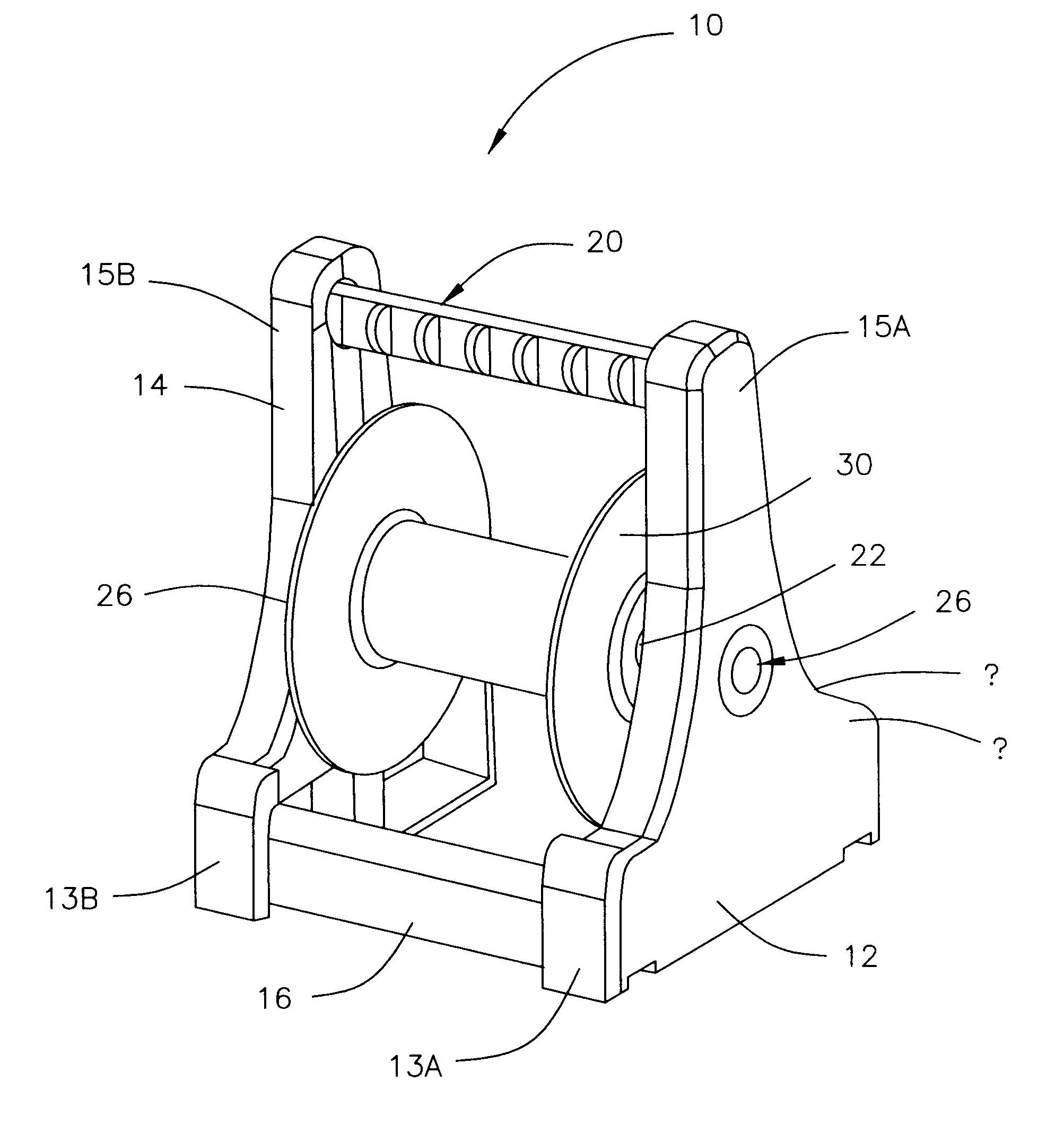
[0025]In one arrangement, as illustrated in FIG. 5, a cable spool payoff stand 10 (stand 10) is shown. Stand 10 includes first and second side bodies 12 and 14. Preferably, sides 12 and 14 are constructed of a strong lightweight polymer that is both stable under the conditions of being loaded with a cable spool, yet light enough to be moved easily around a work site by an installer.

[0026]Sides 12 and 14 are dimensioned to have each have wide base regions 13a and 13b respectively, with tall central columns 15a and 15b respectively. Such shape for sides 12 and 14 provide stand 10 with a wide flat base on either side of a cable spool 30 ensuring that under loaded conditions, the center of gravity for stand 10 is low, preventing the spool from flipping over when an installer is removing cable from stand 10. Tall central columns 15a and 15b, are thin (in keeping with the low flat design) but are strong enough to provide a support for a handle and to prevent the cable from slipping over t...


PUM


Abstract

A stand for delivering coiled cable has first and second side elements, each of which has a wide flat base portion and a tall central column. First and second bottom braces are configured to connect the first and second side elements near the flat base portions. A third handle brace is configured to connect the first and second side elements near the tall central columns. A shaft is configured to be positioned between the first and second side elements, with the shaft configured to receive a cable spool, such that when the spool is positioned on the shaft between the first and second sides, cable from the spool may be allowed to be removed from the spool by spinning the spool on the shaft. The cable can not exit the spool and fall between the outside of the spool and the insides of the first and second side elements.

Description

BACKGROUND[0001]1. Field of the Invention[0002]The present application relates to electrical cable. More particularly, the present application relates to a packaging and dispenser for wire and cable, henceforth referred to as “cable”.[0003]2. Description of Related Art[0004]In the field of cable installation, such as power or signal cables, cable is typically pre-wound on a spool which is in turn set up on an axel, such as a broom handle or pipe, so it can rotate freely, as the cable is withdrawn from the spool during installation. For example with power cable, the spools unwind at the speed with which the installer is pulling the cable through the joist holes. Sometimes when the cable is pulled quickly, the spool continues to turn when the pull is done and the cable will jump off the spool and get tangled on the axel. See for example, prior art FIG. 1 showing such an arrangement.[0005]Moreover, the spool may wander on the axel which further complicates installation. For example, th...

Claims


Application Information

Patent Timeline
Patent Type & Authority Applications(United States)
IPC IPC(8): B65H49/26B65H49/32B65H75/12B65H75/14
CPCB65H49/32
Inventor WIERSTRA, SIDNEY
Owner NEXANS
Why Eureka
Try Eureka