Automated Wafer Container with Equipment Interface

a technology of automatic wafer container and equipment interface, which is applied in the direction of packaging, electrical equipment, other accessories, etc., can solve the problems of requiring manual dexterity of the human hand to open and close the latch, increasing the cost and fragility of semiconductor wafers, and suffering yield loss (around 0.5%) , the problem of significant cost per wafer shipping penalty

Inactive Publication Date: 2014-03-20
KK TECH INC
View PDF0 Cites 12 Cited by
  • Summary
  • Abstract
  • Description
  • Claims
  • Application Information

AI Technical Summary

Benefits of technology

[0022]An equipment interface for the wafer container can provide fully automated operation. The interface can include an automated drawer to accept the wafer carrier from standard factory automated equipment. The drawer can include guide pins to locate the container and keyed actuators to open and close the container latches. The interface c

Problems solved by technology

Semiconductor wafers increase in cost and fragility as they move through the fabrication process.
Despite the perception that these incoming wafer shippers were free, the industry now understands that these containers are not designed for finished wafers and suffer yield loss (around 0.5%) plus a significant cost per wafer shipping penalty.
The opening and closing latches require manual d

Method used


Image

  • Automated Wafer Container with Equipment Interface
  • Automated Wafer Container with Equipment Interface
  • Automated Wafer Container with Equipment Interface

Examples


Embodiment Construction

[0042]Referring to the drawings, wherein like reference numbers are used herein to designate like elements throughout the various views, preferred embodiments of the present invention are illustrated and described. As will be understood by one of ordinary skill in the art, the figures are not necessarily drawn to scale, and in some instances the drawings have been exaggerated and / or simplified in places for illustrative purposes only. One of ordinary skill in the art will appreciate the many applications and variations of the present invention in light of the following description of the preferred embodiments of the present invention. The preferred embodiments discussed herein are illustrative examples of the present invention and do not limit the scope of the invention to the preferred embodiments described.

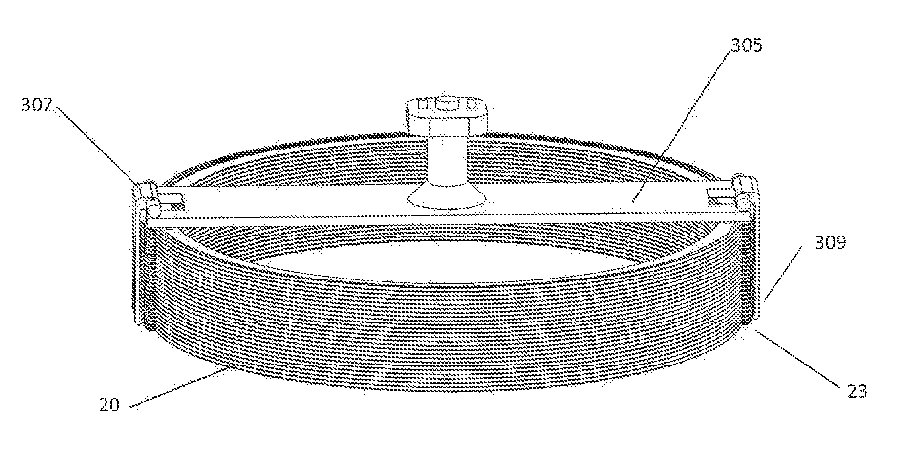
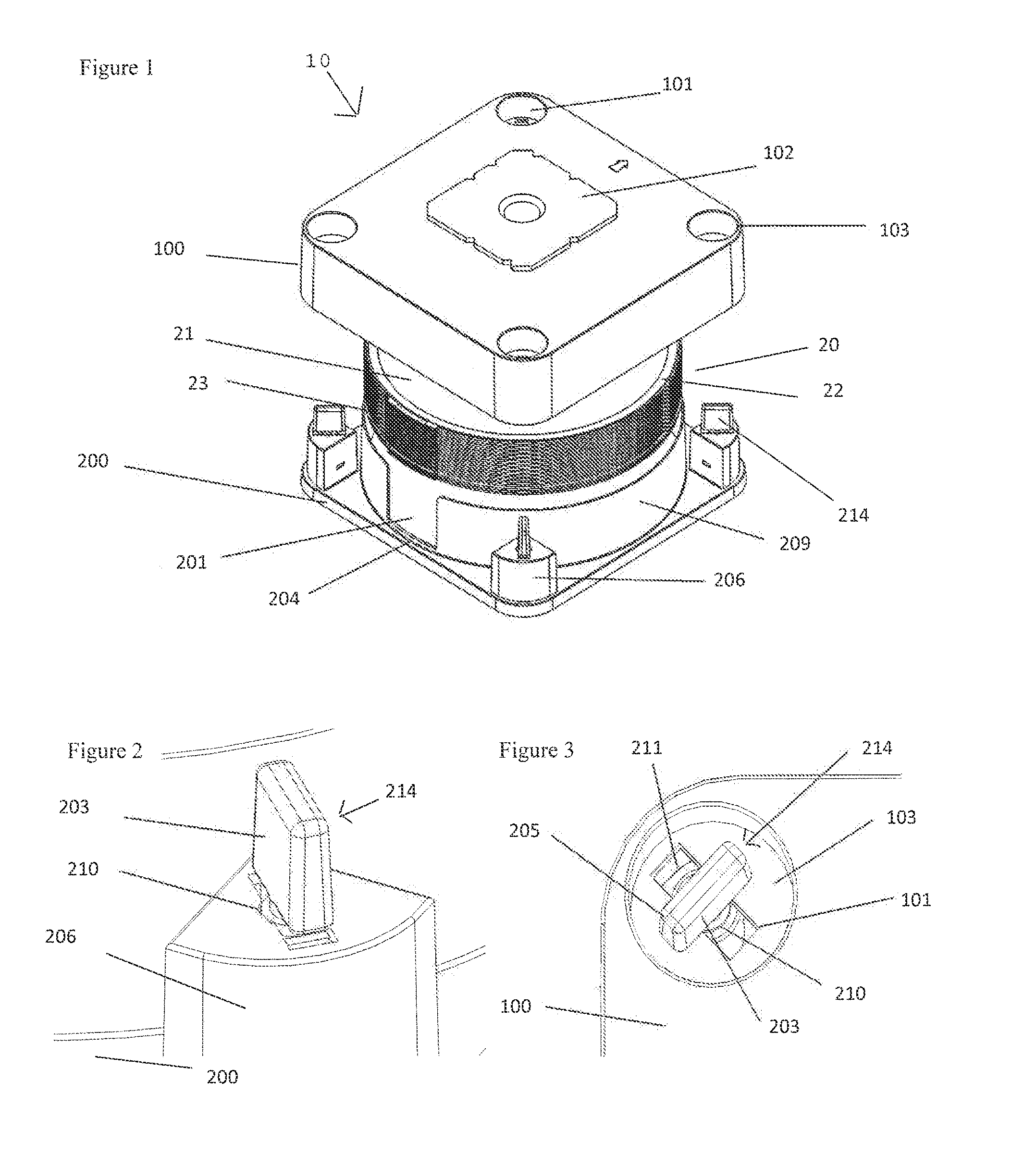
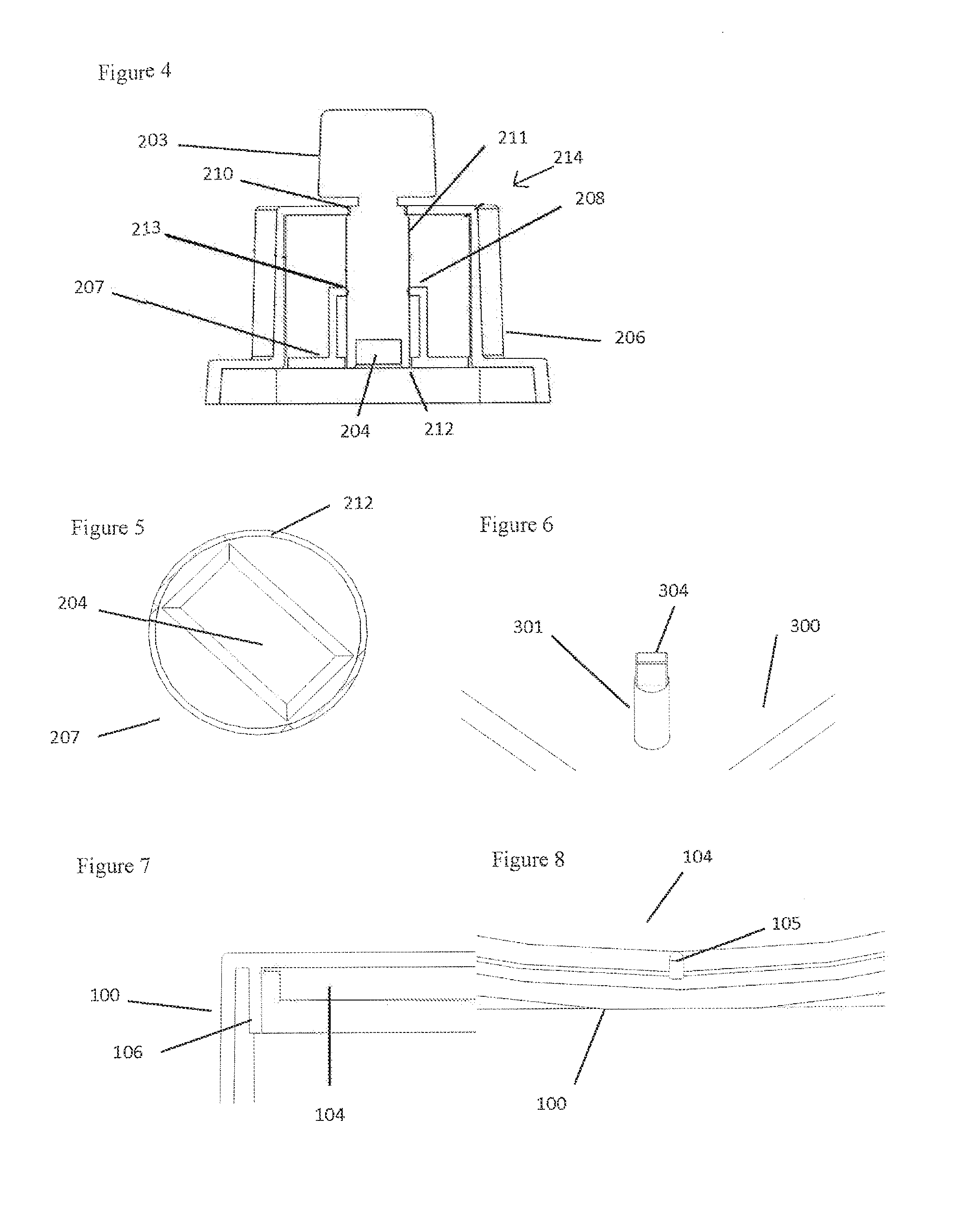
[0043]Referring to FIGS. 1 and 7, a wafer container 10 according to the present invention includes a wafer container lid 100 and base 200, which mate in a clam shell arrangement...


PUM


Abstract

An improved wafer container is provided for use with automated equipment. The container includes a top lid that engages with a bottom base to form a housing having an inner cavity for storing semiconductor wafers. The lid includes a handling member that interfaces with automated equipment for engaging the lid with the base and removing the lid from the base. The container includes latches that can be actuated between a locked position and an unlocked position by automated equipment. The container can hold multiple stacked wafer separator rings, each of which has automation tabs extending outwardly from the ring outer rim. The automation tabs allow for automated equipment to transfer the wafer separators rings between the container and a staging area.

Description

RELATED APPLICATION DATA[0001]This application is based on and claims the benefit of U.S. Provisional Patent Application No. 61 / 702,545 filed on Sep. 18, 2012, the disclosure of which is incorporated herein in its entirety by this reference.BACKGROUND[0002]Semiconductor wafers increase in cost and fragility as they move through the fabrication process. During and after the fabrication process wafers are shipped to other fabrication and assembly / test sites that are often located thousands of miles away. Historically semiconductor manufacturer's reused incoming prime wafer shipper containers to ship finished wafers to other sites because the cost of the shipper container was perceived to be free since it was included in the cost of the incoming silicon. Despite the perception that these incoming wafer shippers were free, the industry now understands that these containers are not designed for finished wafers and suffer yield loss (around 0.5%) plus a significant cost per wafer shipping...

Claims


Application Information

Patent Timeline
IPC IPC(8): H01L21/673
CPCH01L21/67373H01L21/67379H01L21/67772
Inventor KAASHOEK, KURT F.
Owner KK TECH INC
Why Eureka
Try Eureka