
Projector mount

a projector and mount technology, applied in the field of projector mounts, can solve the problems of inability to properly position the projector, and the conventional modification process cannot provide fine-tuned functionality, and achieve the effect of stable structure of the projector mount, convenient modification of the position of the projector, and stable translation fine-tune process

Active Publication Date: 2015-10-20
DELTA ELECTRONICS INC
View PDF31 Cites 7 Cited by
  • Summary
  • Abstract
  • Description
  • Claims
  • Application Information

AI Technical Summary

Benefits of technology

The invention provides a projector mount that allows for easy adjustment of the projector's position in six degrees of freedom. The mount is stable during both translational and rotational fine-tuning. The use of screws and fine-tune screws ensures stability during the fine-tuning process. The technical effect of the invention is that it allows for precise and accurate adjustment of the projector's position.

Problems solved by technology

Conventional projector mounts only provide five degrees of freedom, which cannot position the projector properly.
However, the conventional modification process cannot provide fine-tuned functionality.

Method used


Image

  • Projector mount
  • Projector mount
  • Projector mount

Examples


Embodiment Construction

[0021]The following description is of the best-contemplated mode of carrying out the invention. This description is made for the purpose of illustrating the general principles of the invention and should not be taken in a limiting sense. The scope of the invention is best determined by reference to the appended claims.

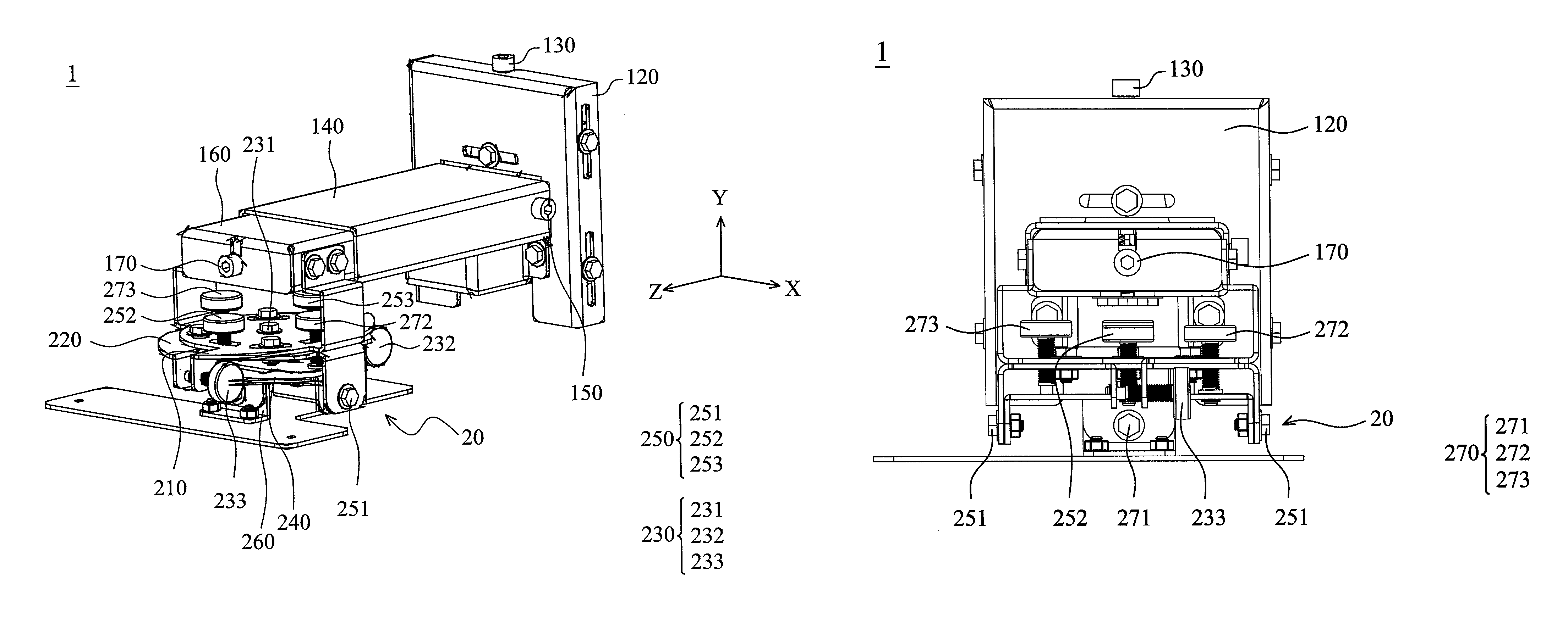
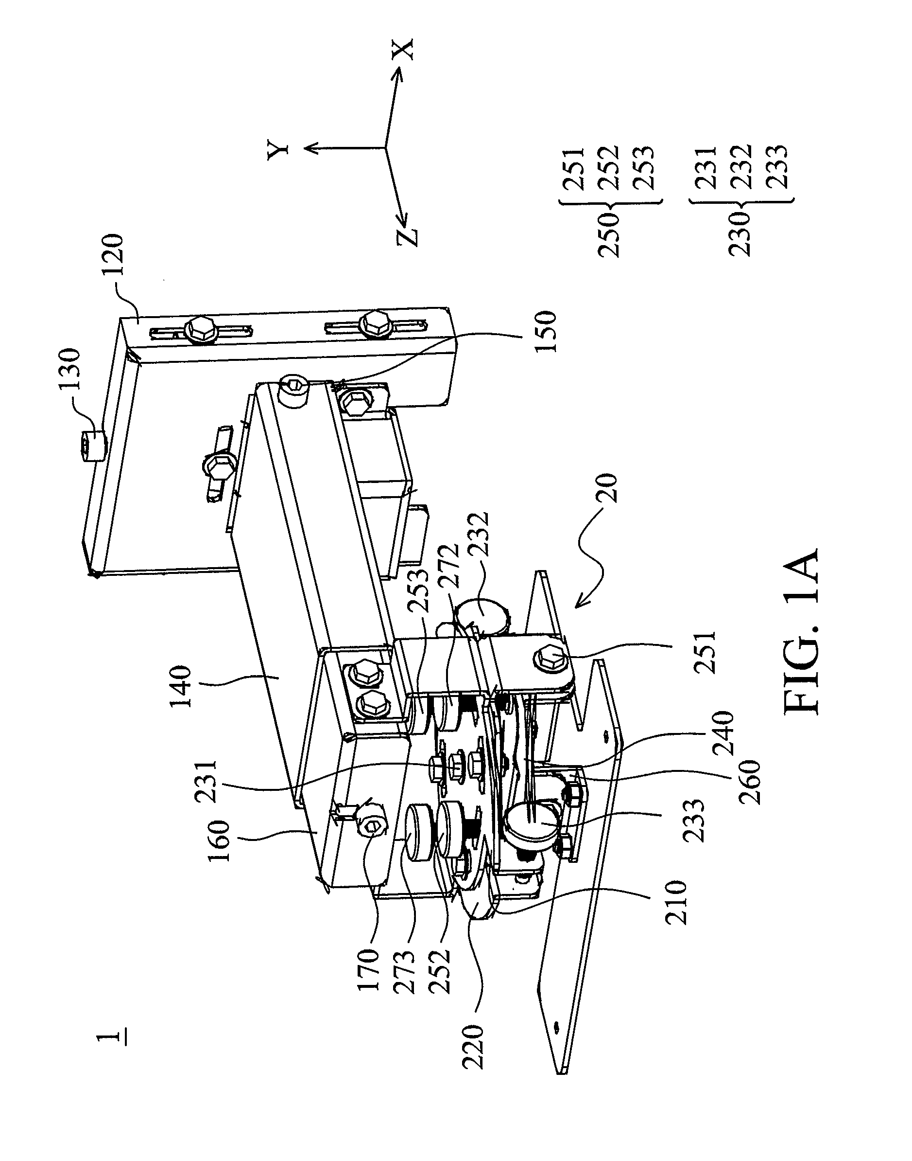
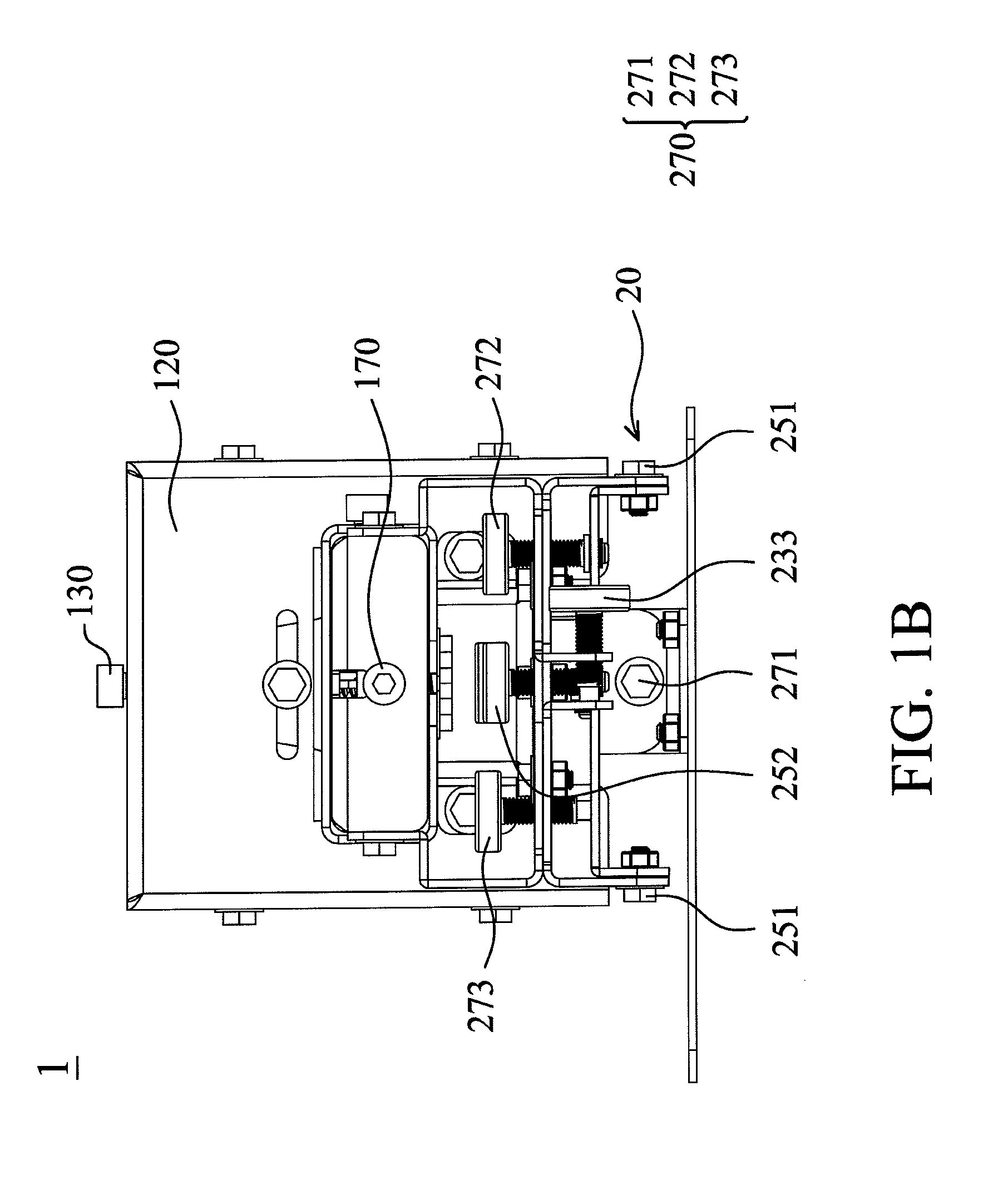
[0022]FIGS. 1A, 1B and 1C show a projector mount 1 of an embodiment of the invention, including a foundation 110, a base 120, a Y axis translation unit 130, a rod 140, an X axis translation unit 150, a telescopic element 160, a Z axis translation unit 170, and an angle adjusting unit 20.

[0023]With reference to FIG. 2A, the Y axis translation unit 130 is connected to the foundation 110 and the base 120, wherein the base 120 is moved in the Y axis relative to the foundation 110 via the Y axis translation unit 130. With reference to FIG. 2B, the X axis translation unit 150 is connected to the rod 140 and the base 120, wherein the rod 140 is moved in the X axis relative to...


PUM


Abstract

A projector mount is provided, which includes a foundation, a base, a Y axis translation unit, a rod, an X axis translation unit, a telescopic element, a Z axis translation unit and an angle adjusting unit. The base is connected to the foundation. The base is moved in the Y axis relative to the foundation via the Y axis translation unit. The rod is connected to the base. The rod is moved in the X axis relative to the base via the X axis translation unit. The telescopic element is connected to the rod. The telescopic element is moved in the Z axis relative to the rod via the Z axis translation unit. The angle adjusting unit is connected to the telescopic element.

Description

CROSS REFERENCE TO RELATED APPLICATIONS[0001]This Application claims priority of Taiwan Patent Application No. 101133915, filed on Sep. 17, 2012, the entirety of which is incorporated by reference herein.BACKGROUND OF THE INVENTION[0002]1. Field of the Invention[0003]The present invention relates to a mount, and in particular to a projector mount.[0004]2. Description of the Related Art[0005]Conventional projector mounts only provide five degrees of freedom, which cannot position the projector properly. The relative angle and position between two parts of the conventional projector mount are changed manually first, and then screwing the two parts together tightly. However, the conventional modification process cannot provide fine-tuned functionality. Additionally, when the two parts are being fixed by screws, the projector may sway and / or swerve, and the shape and dimension of the projection image may be changed.BRIEF SUMMARY OF THE INVENTION[0006]In one embodiment of the invention, ...

Claims


Application Information

Patent Timeline
Patent Type & Authority Patents(United States)
IPC IPC(8): F16M11/12F16M11/24F16M13/02G03B21/54F16M11/20F16M11/04G03B21/14
CPCG03B21/145F16M11/04F16M11/12F16M11/2085F16M11/2092F16M11/24F16M13/02G03B21/54
Inventor CHANG, CHEN-HSIEN
Owner DELTA ELECTRONICS INC
Learn More