Dynamic Bracket System

a bracket system and dynamic technology, applied in the field of dynamic bracket systems, can solve the problems of misalignment of teeth, poor angulation of teeth, and inability to achieve optimal tooth angulation and position, and achieve the effect of improving efficiency and quality of patient care, convenient modification of the position, tip and torque of the bracket slot componen

Inactive Publication Date: 2016-05-26
RAHIMI HESSAM
View PDF1 Cites 5 Cited by
  • Summary
  • Abstract
  • Description
  • Claims
  • Application Information

AI Technical Summary

Benefits of technology

[0009]The dynamic bracket system of the present invention is designed to equip the practitioner with the ability to conveniently modify the position, tip and torque of the bracket slot component during the course of treatment, without having to remove and rebond the bracket. The dynamic bracket system of the present invention increases efficiency and quality of patient care. A dynamic bracket system of the present invention includes a frame, bracket slot component, stationary cover, and a moving cover. The frame, with its textured bottom side, can be bonded to the tooth surface with an adhesive material. The bracket slot component (also referred to as the “bracket”) includes a base, a stem (also referred to as a “neck”) and the top portion of the bracket, which includes an upper arm, a slot, and a lower arm. In some embodiments, instead of upper arm and lower arm designations, the terms arm A, arm B, arm C, and arm D are used.

Problems solved by technology

However, the inaccuracies occurred when a bracket was not bonded to the proper location on the tooth, which led to an improper angulation of the tooth and ultimately to a misaligned tooth.
Whenever a patient's teeth do not fall within the normal range, the straight wire technique does not produce optimum tooth angulation and location.
Commonly, brackets are not always placed in the proper location on the tooth resulting in erroneous bracket positioning.
Repositioning is both time-consuming and expensive and oftentimes does not cure the improperly positioned bracket.

Method used


Image

  • Dynamic Bracket System
  • Dynamic Bracket System
  • Dynamic Bracket System

Examples


Embodiment Construction

[0053]A description of preferred embodiments of the invention follows.

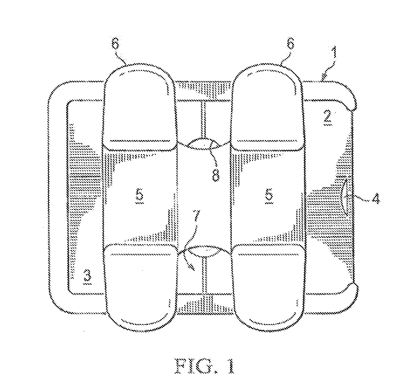
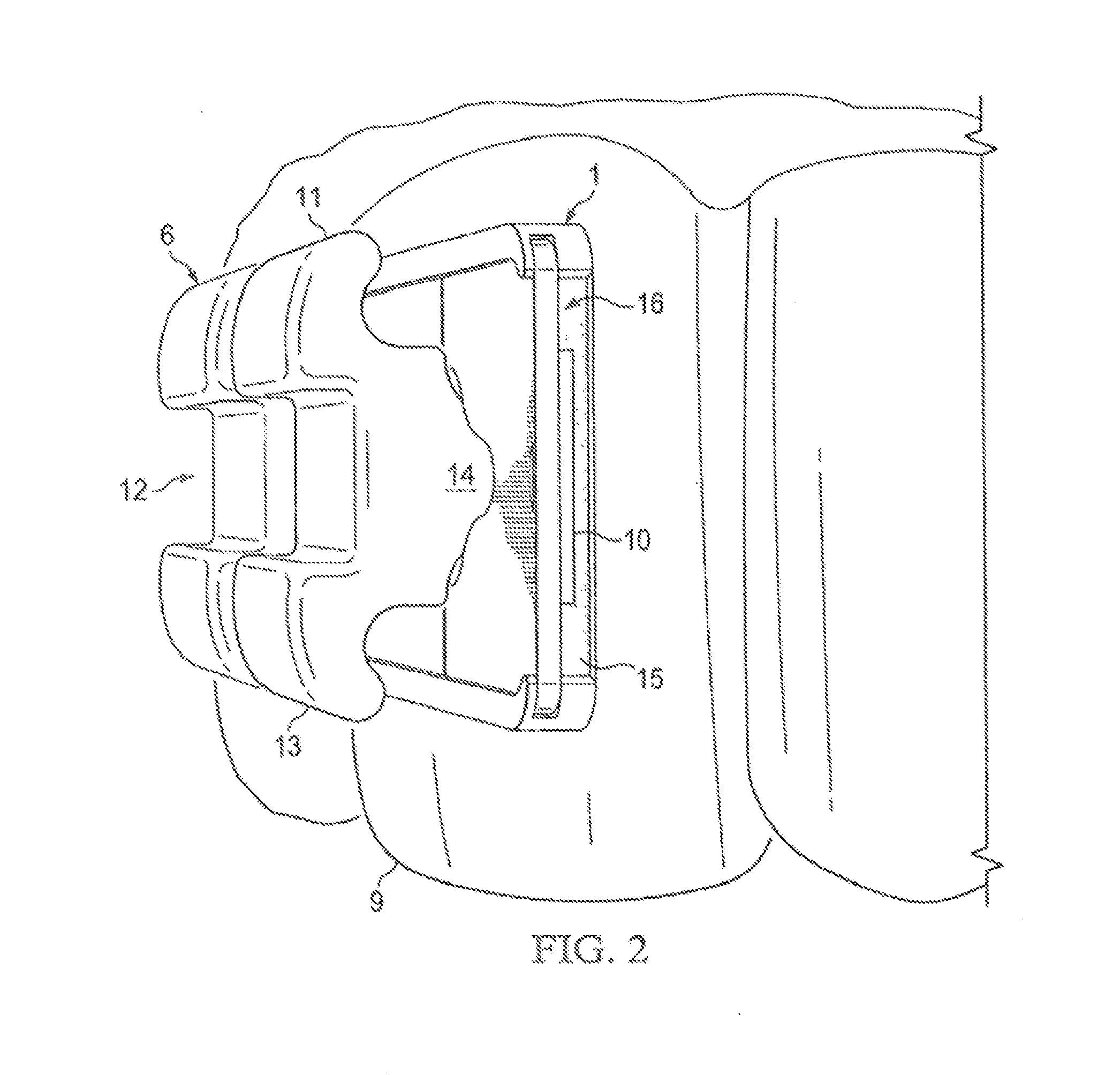
[0054]FIG. 1 is a top view of an embodiment of the dynamic bracket system. The shown dynamic bracket system is composed of a bracket system frame (1) which is connected to the tooth surface (9) (not shown in FIG. 1 but shown in FIG. 2). The interior of the shown frame has grooves or guiding lines (17) for the insertion of the stationary cover and moving cover. See FIG. 4. The moving cover (2) is inserted after the stationary cover (3) into the frame such that the covers connect at a junction (7). The connected covers exert a vertical pressure on the bracket base (10) that helps secure the base inside the bracket compartment (16). The moving cover (2) has a releasing notch (4) into which an orthodontic plier or tool can be inserted in order to release the moving cover from the frame (1). Once the stationary cover (3) is in place within the frame, the bracket slot component (6) is inserted followed by another bracke...


PUM


Abstract

This invention is a dynamic orthodontic bracket system which allows brackets to be adjusted for particular angulations required for each individual tooth of a patient without having to adjust or reposition the frame. The frames are continuously attached to tooth surface. The orthodontist manually adjusts the relationship of a bracket and a frame during treatment eliminating the necessity of a full repositioning of all components. In particular, the bracket can be moved linearly and rotate 360 degrees within the frame. The bracket can be locked or unlocked within the frame with the use of a door and flexible body that acts as a brake. This system leads to lower treatment cost, a more stable bracket system, and quicker adjustments of the orthodontic bracket system.

Description

RELATED APPLICATION[0001]This application is a continuation-in-part of U.S. application Ser. No. 14 / 535,846, entitled “Dynamic Bracket System” by Hessam Rahimi, filed Nov. 7, 2014, which is continuation-in-part of U.S. application Ser. No. 14 / 014,328, now U.S. Pat. No. 9,192,453, entitled “Dynamic Bracket System” by Hessam Rahimi, filed Aug. 29, 2013, which claims the benefit of U.S. Provisional Application No. 61 / 819,536, entitled “Dynamic Bracket System” by Hessam Rahimi, filed May 4, 2013, and is a continuation-in-part of U.S. application Ser. No. 13 / 598,931, now U.S. Pat. No. 9,119,693, entitled “Dynamic Bracket System” by Hessam Rahimi, filed Aug. 30, 2012.[0002]The entire teachings of the above applications are incorporated herein by reference.BACKGROUND OF THE INVENTION[0003]Orthodontics is a specialty in dentistry that moves teeth within the jaw bone and straightens the teeth by moving them to the proper three-dimensional location. In orthodontics, brackets are pieces of met...

Claims


Application Information

Patent Timeline
Patent Type & Authority Applications(United States)
IPC IPC(8): A61C7/14
CPCA61C7/14A61C7/141A61C7/143A61C7/146A61C7/16
Inventor RAHIMI, HESSAM
Owner RAHIMI HESSAM
Why Eureka
Try Eureka