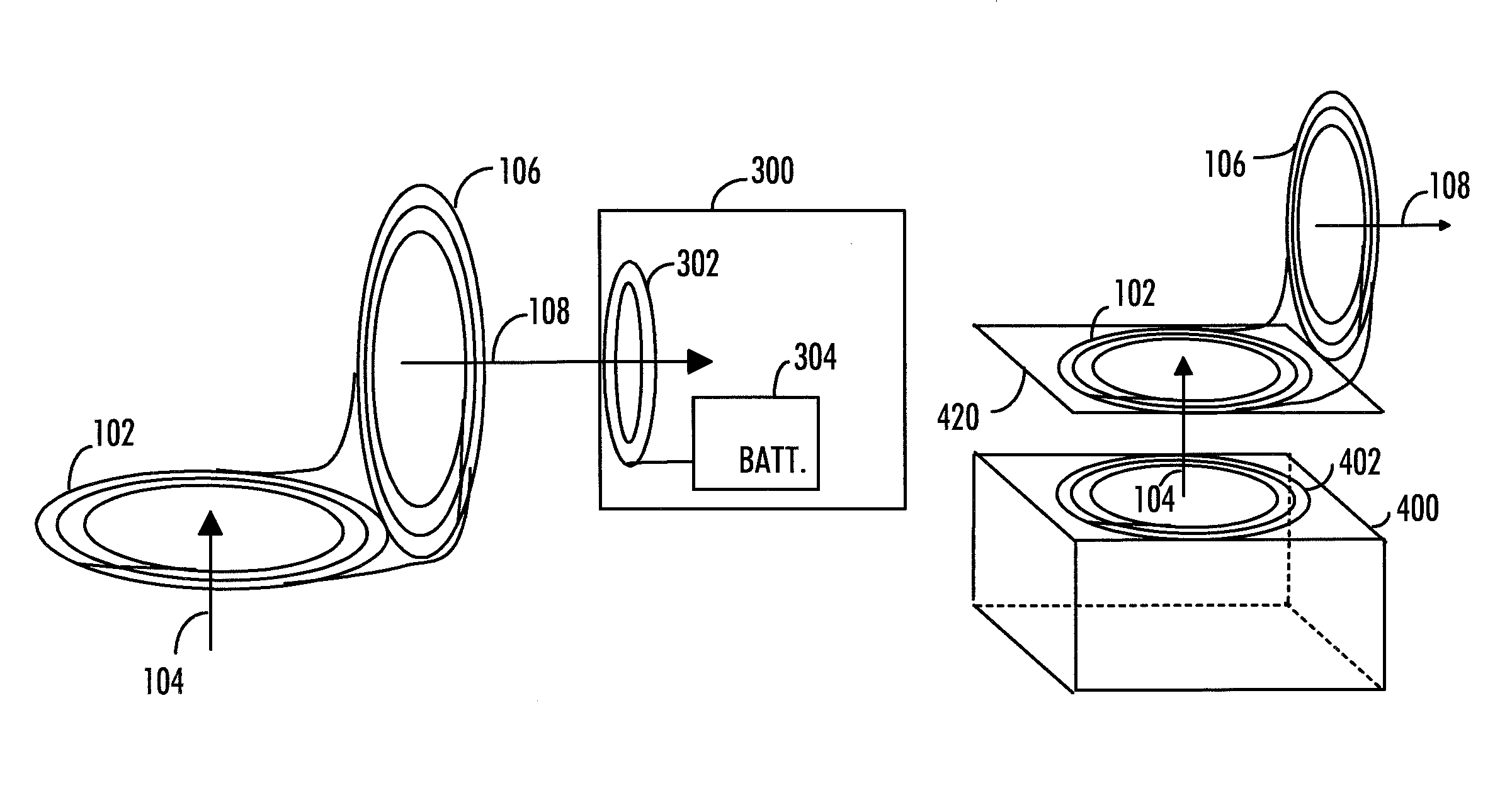
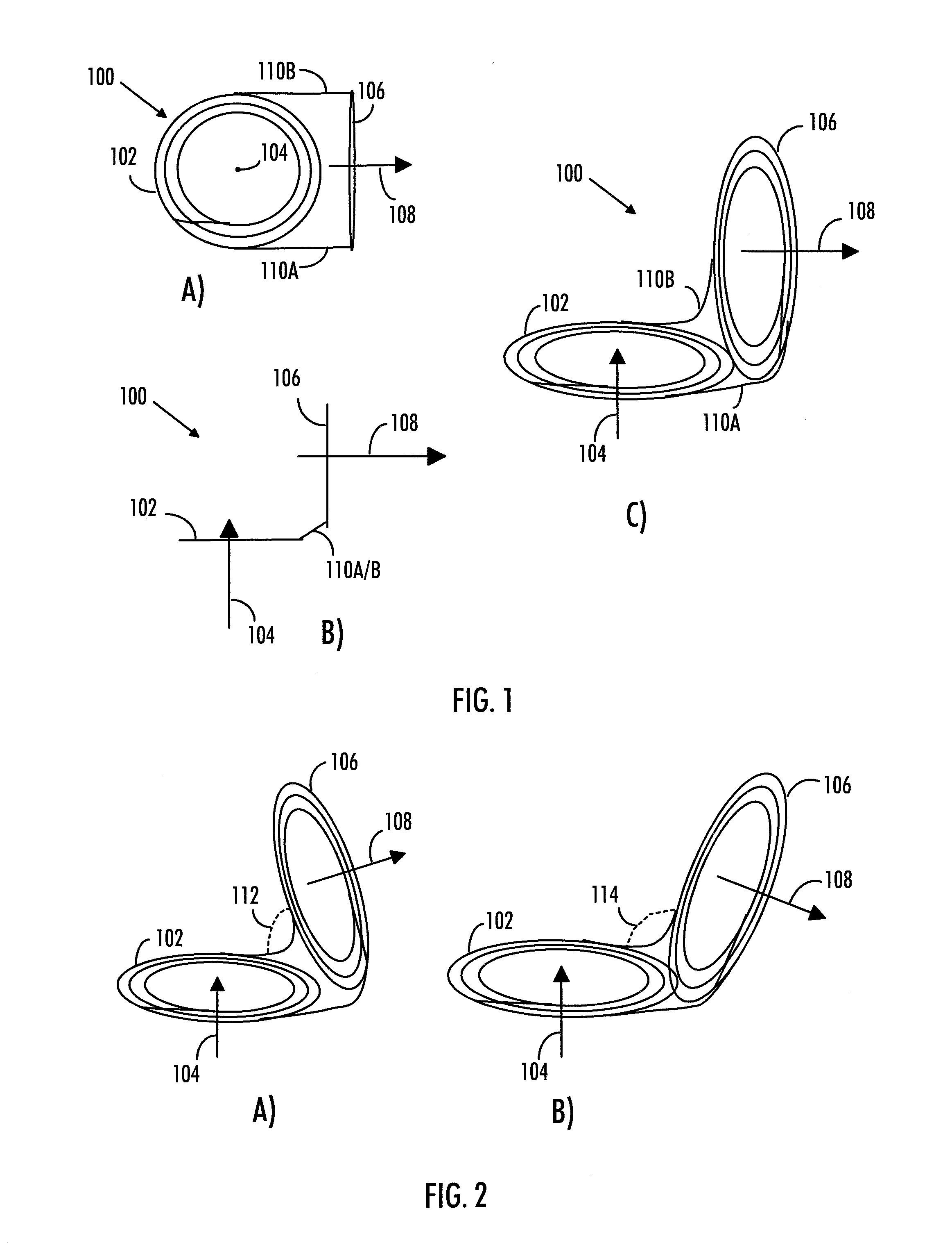
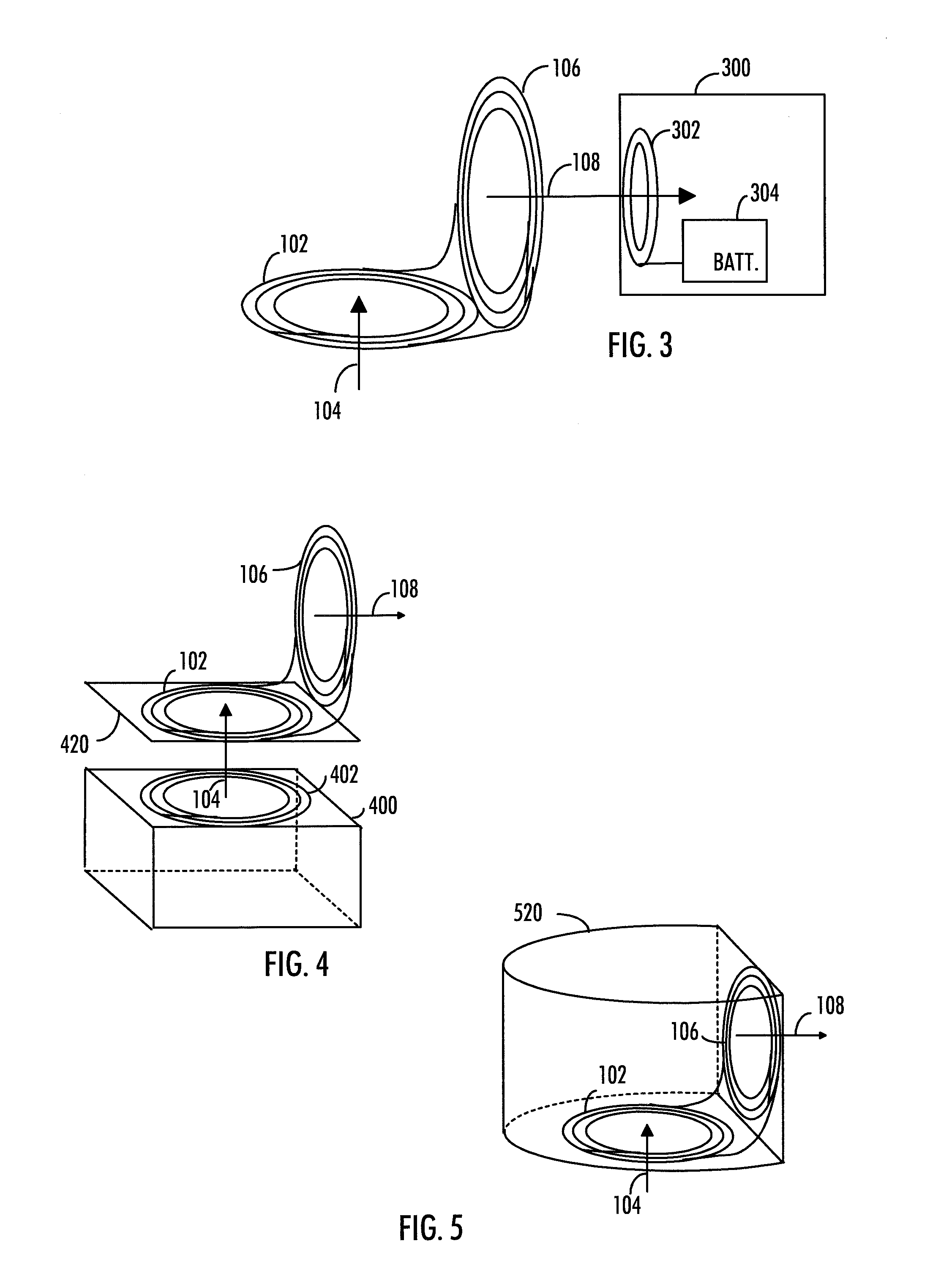
Wireless power transfer device that redirects a magnetic flux
a technology of wireless power transfer and magnetic flux, which is applied in the direction of inductance, transportation and packaging, electrochemical generators, etc., can solve the problems of several types of charging, and achieve the effect of improving the applicability of wireless charging
- Summary
- Abstract
- Description
- Claims
- Application Information
AI Technical Summary
Benefits of technology
Problems solved by technology
Method used
Image

Examples
Embodiment Construction
[0020]The following embodiments are exemplary. Although the specification may refer to “an”, “one”, or “some” embodiment(s) in several locations of the text, this does not necessarily mean that each reference is made to the same embodiment(s), or that a particular feature only applies to a single embodiment.
[0021]According to electromagnetic induction theory, an alternating external magnetic flux induces a voltage to a conductor, such as to a coil. The voltage induced to the coil is given by e=−NAdB / dt, where B is the density of the magnetic field, A is the surface area of the coil, and N is the number of loops in the coil. The minus sign denotes that the polarity of the induced voltage e is such that it drives such an electric current to the coil that a magnetic field generated by the electric current opposes the change in the magnetic flux which produced the voltage e. Therefore, the induced electric current may generate another magnetic field that is oriented in the direction of ...
PUM
| Property | Measurement | Unit |
|---|---|---|
| electric current | aaaaa | aaaaa |
| angle | aaaaa | aaaaa |
| rotation | aaaaa | aaaaa |
Abstract
Description
Claims
Application Information