Hot channel distributor arrangement for a hot channel system

Active Publication Date: 2015-11-03
EWIKON HEIBKANALSYSTEME GMBH
View PDF17 Cites 1 Cited by
  • Summary
  • Abstract
  • Description
  • Claims
  • Application Information

AI Technical Summary

Benefits of technology

[0007]An illustrative hot channel distributor arrangement may include one or more main distributor block configured to pivot about a first rotational axis. Each main distributor block may include at least one main distributor arm. An auxiliary distributor block may be arranged on each main distributor arm of each main distributor block and rotatable with respect to the main distributor arm about a respective second rotational axis. A nozzle arrangement may be provided on each auxiliary distributor block. The relative position at least between the main and auxiliary distributor block/blocks or the respective arms may be fixed in a clamping fashion only in the heated operating state of the hot channel system by thermal expansion directly in the region of the second rotational axes. In the cold state and during a heating phase of the hot channel distributor arrangement, a change in the angular position between the main distributor arm and the auxiliary distributor arm which is arranged there

Problems solved by technology

The limited local mobility of the nozzle arrangements and bodies is an impediment to many applications.
Also, the fixing of the nozzle arrangement in its end position for performing the actual injection process is inadequate for the prevailing high pressures.
In particu

Method used


Image

  • Hot channel distributor arrangement for a hot channel system
  • Hot channel distributor arrangement for a hot channel system
  • Hot channel distributor arrangement for a hot channel system

Examples


Example

DETAILED DESCRIPTION OF THE DRAWINGS

[0041]In so far as terms such as “top”, “bottom”, “horizontal” etc. are used, they relate to the respective illustration in the drawings and shall not be understood in any limiting way and shall respectively be applied accordingly to other positions of the arrangements. Specialist terms shall be understood in their usual specialist way, unless defined otherwise in connection with this application.

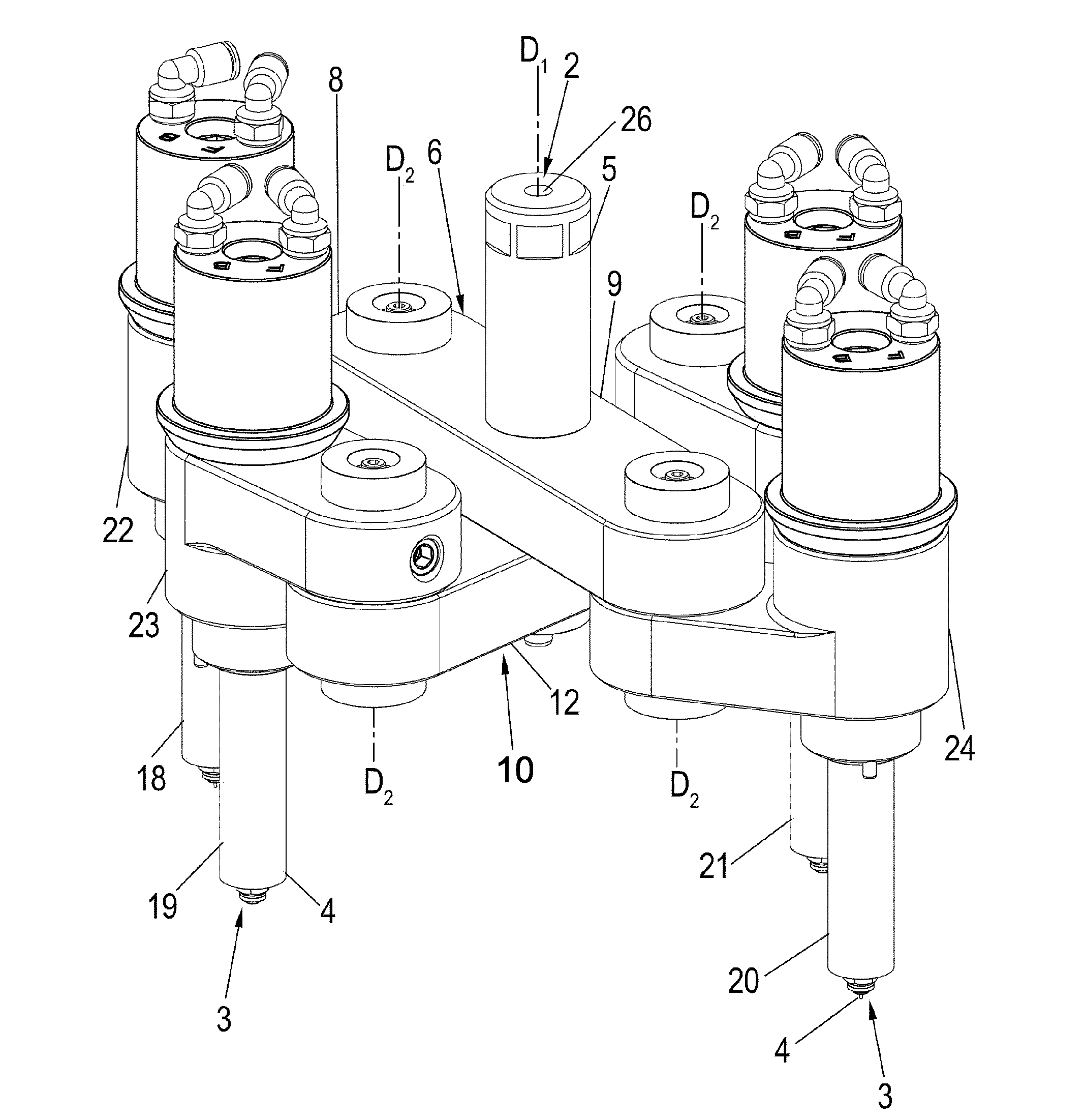
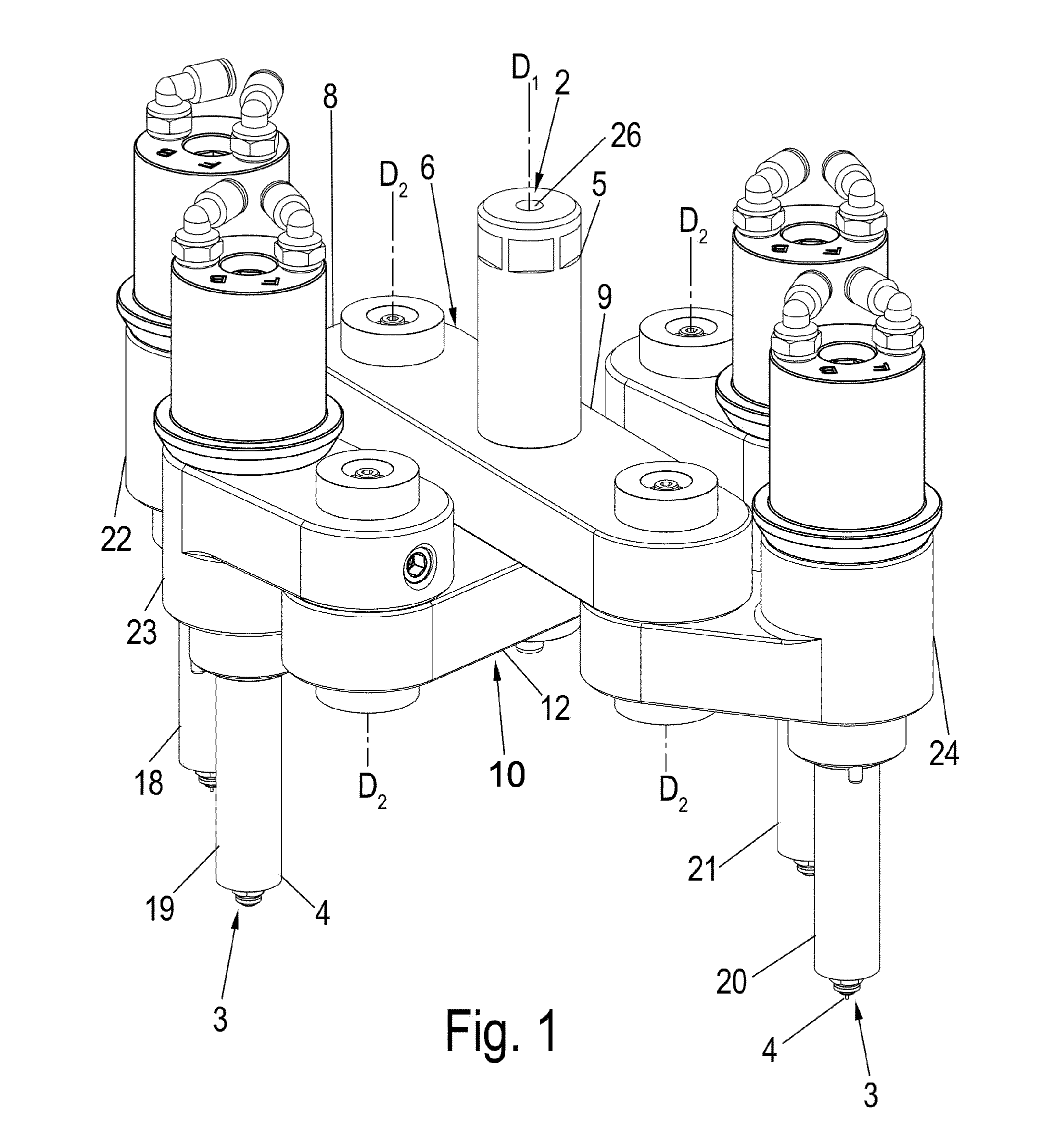
[0042]FIG. 1 discloses a hot channel distributor arrangement 1, which can be used on or in a hot channel system. Reference is further made to FIG. 13, which shows the hot channel distributor arrangement 1 in a hot channel system or in a state inserted in a surrounding hot channel distributor channel system.

[0043]The hot channel distributor arrangement 1 may be used for feeding a plastic melt, which enters a pour-in opening 2 of the hot channel distributor opening, to at least one or several outlet openings 3 to which the plastic melt is respectively condu...


PUM

PropertyMeasurementUnit
Angleaaaaaaaaaa
Temperatureaaaaaaaaaa
Angleaaaaaaaaaa

Abstract

A hot channel distributor arrangement for a hot channel system that can particularly be heated during a heating phase, which is designed to supply plastic melt from a pour-in opening for at least two nozzle arrangements that can be moved relative to and independently of one another, each having at least one outlet opening in the region of a nozzle body, wherein at least one main distributor block having at least one main distributor arm is provided, said main distributor block being rotatable around a first rotational axis, wherein at least one auxiliary distributor block is arranged on the at least one main distributor block, said auxiliary distributor block forming at least one auxiliary distributor arm and being rotatable around a second rotational axis, wherein an angle between the main distributor block and the auxiliary distributor block is adjustable, wherein at least one of the nozzle arrangements is provided on each auxiliary distributor arm, and wherein the angle between the main distributor arm and auxiliary distributor arm changes due to thermal expansion at least during the heating phase.

Description

BACKGROUND OF THE DISCLOSURE[0001]The disclosure relates to a hot channel distributor arrangement for a hot channel system.[0002]Reference is made at first to DE 29 38 832 concerning the general technological background of the technology of hot channel systems.[0003]In order to injection-mold several mold cavities, several nozzle arrangements are required, which are optionally provided with sealing needles, whose positions are to be adjusted to those of the respective mold cavities.[0004]A hot channel injection system is described in U.S. Pat. No. 5,540,580, which is configured for so-called “blow molding”, i.e. for a blow injection method, in order to produce hollow containers such as plastic bottles. It is disclosed in U.S. Pat. No. 5,540,580 that several distributor blocks can movably be arranged with respect to each other, wherein the pressing pressure between the inlet or pour-in opening of the main distributor channel system and the only outlet can be used in order to seal the...

Claims


Application Information

Patent Timeline
IPC IPC(8): B29C45/22B29C45/27B29C45/26
CPCB29C45/2738B29C45/2727B29C2045/2683B29C2045/2717B29C2045/2729
Inventor EIMEKE, STEFANPOMSTRA, HENK JAN
Owner EWIKON HEIBKANALSYSTEME GMBH
Why Eureka
Try Eureka