
FBMC receiver with carrier frequency offset compensation

a carrier frequency offset and receiver technology, applied in the field of telecommunication systems, can solve the problems of loss of spectral efficiency, inability to effect and inability to achieve the effect of offset compensation on the upstream connection of the fbmc receiver

Active Publication Date: 2015-11-03
COMMISSARIAT A LENERGIE ATOMIQUE ET AUX ENERGIES ALTERNATIVES
View PDF2 Cites 8 Cited by
  • Summary
  • Abstract
  • Description
  • Claims
  • Application Information

AI Technical Summary

Problems solved by technology

The insertion of a guard time or a prefix does however lead to a loss of spectral efficiency.
Finally, since the spectral occupation of an OFDM signal is substantially greater than the subcarrier band that it uses because of the spread of the secondary lobes, OFDM modulation is not an optimum solution for applications requiring high off-band rejection levels.
One of the problems encountered in FBMC systems is compensating for the carrier frequency offset at the receiver.
However, this FBMC receiver does not make it possible to effect an offset compensation on the upstream connection except in a single-user context.
This is because, when several terminals share the subcarrier multiplex in order to transmit to a base station, it is not possible to compensate individually and independently for the offsets between the demodulation frequency of the receiver (of the base station) on the one hand and the carrier frequencies of the various transmitters (of the terminals) on the other hand.
It does not make it possible to compensate for the interference between sub-channels when the frequency offset can no longer be ignored with regard to the difference in frequency, ΔFc=1 / T, between these sub-channels.

Method used


Image

  • FBMC receiver with carrier frequency offset compensation
  • FBMC receiver with carrier frequency offset compensation
  • FBMC receiver with carrier frequency offset compensation

Examples


Embodiment Construction

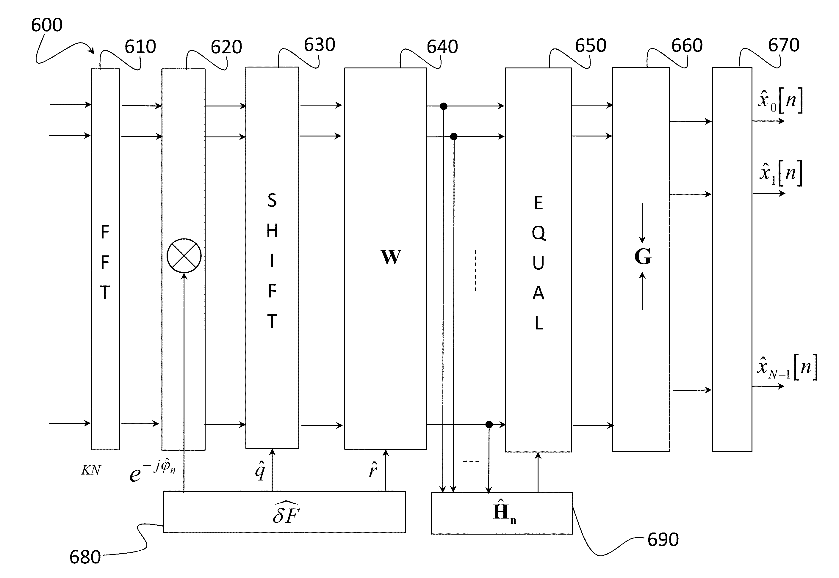
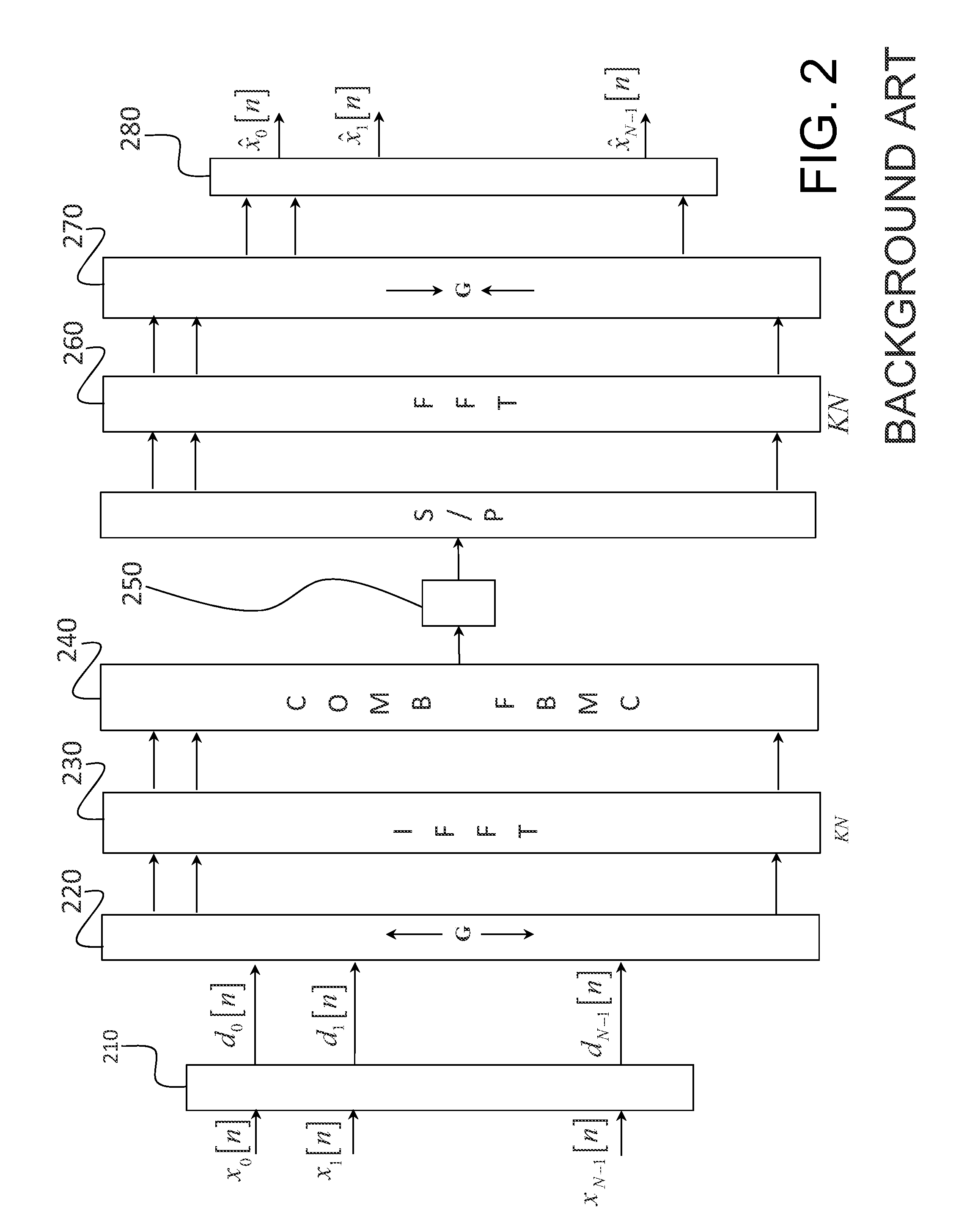
[0081]We shall consider hereinafter an FBMC receiver implemented in the frequency domain, as described in relation to FIG. 2. The idea at the basis of the invention is to effect in an original manner the correction of offset in the frequency domain, at the output of the FFT.

[0082]It will be assumed first of all that the receiver receives FBMC symbols only from one user (the case of the downstream connection for example or of a single user on the upstream connection).

[0083]The signal received by the receiver, after base-band demodulation, is sampled at the frequency Nf and the samples obtained are subjected to a sliding FFT, of size KN, where N is the number of sub-channels (or in an equivalent manner the number of synthesis / analysis filters) and K is the overlap factor of the FBMC transmitter.

[0084]dn means the vector of the data, or more precisely the vector of the OQAM symbols di[n]i=0, . . . , N−1, transmitted by the transmitter, that is to say dn=(dO[n], . . . , dN−1[n])T.

[0085]...


PUM


Abstract

A filter bank receiver (FBMC) effecting a carrier frequency offset compensation in the frequency domain. The receiver comprises an FFT module extended by the overlap factor (610), a module (630) offsetting a predetermined number of subcarriers at the output of the FFT followed by a filter for reducing interference between subcarriers (640), the number of subcarriers and the coefficients of the interference reduction filter being determined from an estimation () of the frequency offset. The vector of samples thus obtained is then the subject of channel equalisation (650) before being filtered by a battery of analysis filters and spectrally de-spread (660). Finally, after spectral de-spreading, the vector of samples is demodulated by an OQAM demodulation (670) so as to recover the transmitted data.

Description

TECHNICAL FIELD[0001]The present invention concerns in general terms the field of telecommunication systems using filter bank multicarrier (FBMC) modulation.PRIOR ART[0002]Telecommunication systems using multicarrier modulation are well known in the prior art. The principle of such modulation consists of dividing the transmission band into a plurality of frequency sub-channels associated with subcarriers and modulating each of these subcarriers by data to be transmitted.[0003]The most widespread multicarrier modulation is without any doubt OFDM (Orthogonal Frequency Division Multiplexing) modulation. This is used in wireless local networks (WLAN), WiFi, in high bit rate wireless internet access (WiMAX), digital radio broadcasting systems (DVB-T, ISDB-T, DAB), asymmetric digital links (xDSL), fourth generation cellular telephony (LTE), etc.[0004]In an OFDM transmission system, each block of OFDM symbols is preceded by a guard time or a cyclic prefix, with a length greater than the ti...

Claims


Application Information

Patent Timeline
Patent Type & Authority Patents(United States)
IPC IPC(8): H03D1/06H04L25/03H04L27/26
CPCH04L25/03159H04L27/2601H04L27/264H04L27/2657H04L27/2654H04L27/26416
Inventor DORE, JEAN-BAPTISTECASSIAU, NICOLAS
Owner COMMISSARIAT A LENERGIE ATOMIQUE ET AUX ENERGIES ALTERNATIVES
Learn More