Airboat braking system

a technology for airboats and braking systems, applied in the direction of air acting propulsive elements, marine propulsion, vessel construction, etc., can solve the problems of the operator endangering the people on the airboat, and achieve the effect of slowing down the boat and increasing drag

Active Publication Date: 2015-11-10
DURAND ROGER
View PDF12 Cites 4 Cited by
  • Summary
  • Abstract
  • Description
  • Claims
  • Application Information

AI Technical Summary

Benefits of technology

[0013]The device itself will be mechanically linked so that each plate can operate independently of each other. The control arm for the operation of the braking system will be spring loaded so that the plates would ordinarily be in a position above the water so it does not create any undue stress on the boat.

Problems solved by technology

One of the challenges is being able to safely stop an airboat and perhaps steer the boat.
If an individual does not necessarily know how to operate an airboat, it may create a situation where the operator endangers the people on the airboat by moving too fast through the water or perhaps not be able to control the boat.

Method used


Image

  • Airboat braking system
  • Airboat braking system
  • Airboat braking system

Examples


first embodiment

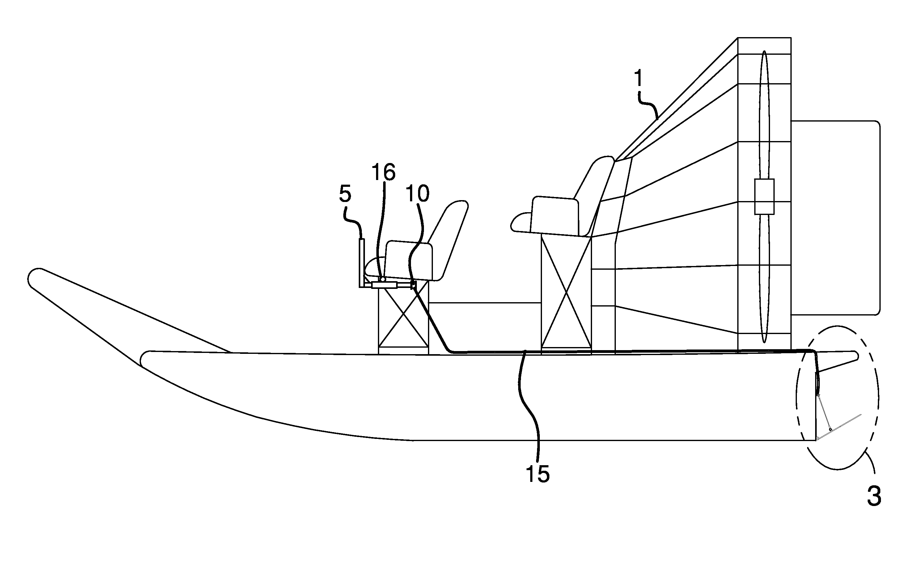
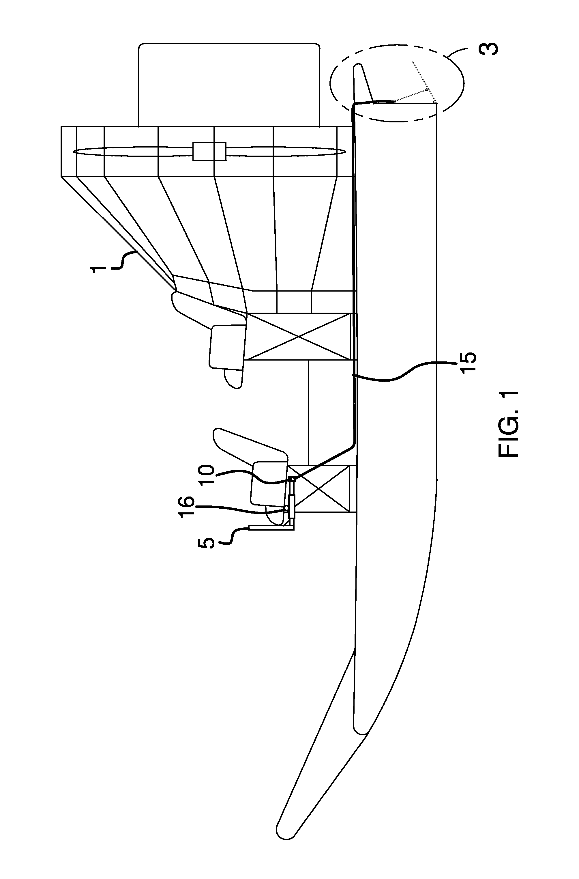
[0035]This is a device that will be installed on the stern of an air boat 1 and which is operated by a control arm 5 by the operator of the airboat.

[0036]The control arm 5 is linked to an interior tube 17 that rotates freely within an outer tube 19; the interior tube 17 extends a predetermined distance and secures a bracket 18. On the ends of the bracket 18 will be means to attach a pair of first linkage cables. The control arm 5 can be moved up or down or side to side.

[0037]A mounting piece 16 secures the brake to the underside of the seat of the airboat. The mounting piece 16 is secured to the outer tube 19 that houses the interior tube 17 such as depicted in FIG. 5.

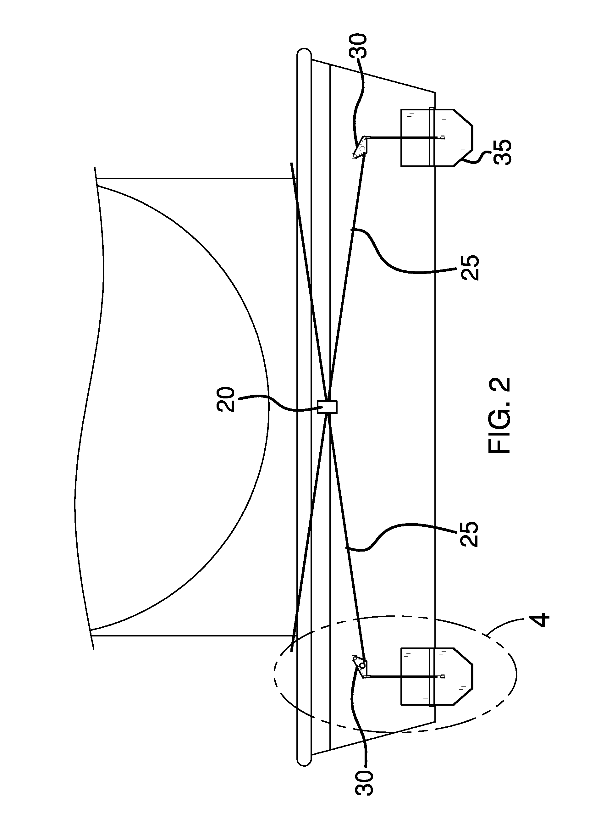
[0038]If the control arm 5 is moved directly up or down the brake plates through appropriate linkage will deploy and strike the water at the same time. If the control arm 5 is rotated from side to side the interior tube 17 will rotate the bracket and in turn will move either the cable on the right or on the left either...

second embodiment

[0050]In an ice environment the brake plate 35 will have a series of spikes on the surface to strike the ice when the brake plate is positioned such that it will grip the ice in order to stop the boat or make the boat turn left or right.


PUM


Abstract

One of the challenges in the operation of an airboat is to insure that the boat can be stopped quickly and safely and can turn left or right as needed. This is compounded by the fact that airboats typically move on the top surface of the water and there is very little boat surface below the surface of the water. With this system a pair of brake plates are positioned on the stern of the airboat and can be rotated in a downward fashion to strike the water surface in order to stop or turn the airboat in a safe, controlled fashion.

Description

BACKGROUND OF THE INVENTION[0001]A. Field of the Invention[0002]This relates to the ability of an ability to brake an airboat. Airboats have unique challenges because there is no propeller in the water and all braking is done either by slowing the boat down or by essentially stopping the engine. However, this may leave the person at risk for being able to maneuver the vessel if there are rough seas.[0003]B. Prior Art[0004]This is a device that will be used to help control the forward movement of an airboat. Airboats, unlike a typical boat rests on the top surface of the water and has very little draft or depth below the surface of the water. This type of boat is ideal for use in shallow water that can be found in swamps.[0005]However, because the water is shallow it is very difficult to stop the boat in the event of an emergency.[0006]There are prior art references that deal with systems for airboats and these can be found at Bootes, U.S. Pat. No. 7,007,621 and Schad, U.S. Pat. No. ...

Claims


Application Information

Patent Timeline
Patent Type & Authority Patents(United States)
IPC IPC(8): B63H25/48B63H25/44B63H7/00
CPCB63H25/44B63H7/02
Inventor DURAND, ROGER
Owner DURAND ROGER
Why Eureka
Try Eureka