
Trim tabs and surface drive propeller bite control

a technology of surface drive and trim tabs, which is applied in the direction of marine propulsion, special-purpose vessels, vessel construction, etc., can solve the problems of limited effectiveness of "up on the tabs" operation of prior art trim tabs, and ambiguous "trim angle" that leads to deflecting the rear of the boat up or down,

Inactive Publication Date: 2002-11-28
VON WOLSKE JAMES P
View PDF5 Cites 43 Cited by
  • Summary
  • Abstract
  • Description
  • Claims
  • Application Information

AI Technical Summary

Benefits of technology

[0042] Of particular interest to dual surface drives with opposite rotation, the integrated surface drive and trim tabs in accordance with the present invention reduces yaw of the surfacing propeller and the sporadic side crawl forces by balancing these forces in opposition to each other. In particular, the bite of each propeller is closely controlled under all conditions to reduce the sporadic forces. The use of bite control and engine speed synchronizers tends to decrease the problem of unbalanced yaw forces.
[0044] In a different application, the integrated surface drive and trim tab configuration may be employed to utilize yaw as a high speed steering mechanism, which is particularly suited for drag boats which run in a straight line. In one embodiment, this is accomplished by using a single engine with dual drive counter rotating surface drives. With this arrangement, the thrust tubes do not actually sweep left or right as part of the steering, but rather, the bite for each drive is moved down or up to add more or less thrust to either side of the boat. The differential bite mode of steering changes the direction of the boat travel by small increments while traveling at high speeds. One advantage to this is that the steering is accomplished using the existing hardware in a simplified form and there is no drag from a rudder. Another advantage is that the motor can be revved up to high speed with the propellers pulled out of the water and then dropped into the water at the green light, similar to revving up a car engine and dropping the clutch in a street drag race. Low speed maneuvering is accomplished by a simple low speed, swing down, rudder which can be controlled by the driver. At high speeds, the rudder swings up out of the water to minimize drag and therefore transfers steering authority to the bite control mechanism.
[0045] Historically, in emergency situations, such as, for example, the loss of a rudder, yaw control for steering of dual propeller boats was accomplished by slipping one clutch or slowing one engine relative to its sister. In contrast, the present invention allows drag racers the use of differential bite control of the propellers, which are spinning at the same speed, to steer the boat as the normally intended mode of operation. In this application, much of the weight of a gimble and universal joints can be eliminated if a coupling, such as a roller chain type, or gear and sleeve type, is used to connect the drive shaft to the propeller shaft. Due to their loose fit, these types of couplings have sufficient flexibility to allow the necessary up and down swing of the propeller shaft.
[0047] In one embodiment, the ever present danger from the exposed propeller is decreased by the addition of a people guard which covers the blades at low speed and retracts at high speed so as not to impair the full performance of the propeller.

Problems solved by technology

The term "trim angle" often leads to ambiguity as to whether it is the angle of the boat, or the tabs, or the outdrive being discussed.
When underway, water rushes under the boat, causing the rear of the boat to be deflected up or down by the trim tabs.
It is noted, however, that the "up on the tabs" operation of prior art trim tabs has limited effectiveness.
Leaning may be due to propeller torque, uneven weight distribution, or cornering.
Prior art trim tabs are only somewhat effective in changing the attitude of the boat.
A major deficiency of flat plate hinged tabs is that the up tab position causes an abrupt change in the contour of the surface running on the water.
As with any airfoil, flow separation causes loss of lift.
The hinged flat plate is simply a crude airfoil with poor lift to drag ratio and is not very successful at raising the nose of the boat.
Although somewhat superior to hinged plate designs, the bending flat plate also has excessive drag for the amount of lift generated.
This method of changing the attitude of the boat and lifting or depressing the stem of the boat by changing the thrust angle of the propulsion is not as efficient as optimizing the thrust vector to be essentially parallel to the direction of travel and then adjusting the hull geometry to optimize the hydrodynamic lift to drag ratio.
The steering sweep is somewhat effective, but the vertical sweep for controlling trim is rather deficient.
The skeg is also intended to contribute to the steering, but because a surface drive has a steerable thrust vector, the skeg has only a minimal contribution to the steering, especially when under power.
The skeg imposes undesirable drag and also slices a groove in the water as the water approaches the propeller blades.
In this manner, the skeg causes a major disruption in the homogeneous flow field of water into which the blades are progressing as the is propeller screws itself into the water.
Although there is a performance penalty due to the drag forces of the skeg in the water, there is an added performance penalty over and above that simple drag force due to the field disruption and aeration of the water ahead of the propeller.
A propeller designed to be nonventilating does not work well in a ventilating mode and conversely, a propeller designed to operate in the ventilating mode, which is sometimes referred to as "hyperventilating" mode, does not work well in a nonventilating mode.
Surface drives have a disadvantage of not backing up very well.
This is caused by the propeller back wash impinging on the transom of the boat and nullifying the reversing thrust.
Surface drives also have a disadvantage of presenting an exposed propeller at the surface of the water such that a passenger could fall into contact with the blades more easily than with submerged propeller type of drives.
However, as previously discussed, the vertical thrust vectoring of the propulsion system is inefficient compared to the preferred trimming of the hull through the use of trim tabs.
Using the up trim on a surface drive has a very weak effect on the attitude of the boat and usually only tends to pull the propeller too far out of the water causing the engine to overspeed.
Using the down trim immerses the propeller too far into the water causing the engine to slow down due to overload.
The difficult part of controlling this bite is that the water depth on the surfacing propeller is influenced by wave action, boat bounce, cornering, or speed changes.
However, sporadic changes in bite are not desirable because it is hard on the drive train, it makes the boat difficult to control, and it may be dangerous to the occupants.
Another disadvantage of surface drives is that they tend to crawl sideways due to having only the lower half of the propeller in the water, which thus imparts a net sideways force on the propeller.
This side motion can be chronic, unpredictable, and fatiguing to the driver.
Another disadvantage of surface drives is that the boat tends to struggle to get up on plane.
Because the torque output of an engine is low at low revolutions per minute (RPM) and because the propeller is fully immersed, or "flooded", at low speeds, surface drive boats often have a difficult time getting over "hump speed", which is that speed when the boat actually starts to plane and the drag forces tend to decrease.
Another disadvantage with surface drive boats is they may tend to "blow over" at high speeds.
Although other high speed boats also blow over, the surface drive may be worse in that, as the bow of the boat starts to rise up, the extended propeller is dunked under the water surface as the boat tends to rise up on its bottom surface at the stern thus adding to the blow over condition.
Prior boat designs do not address the changing bite associated with wave action, or hull bounce, or changes in speed, or the fact that the plane of water leaving the bottom of the craft when turning is not in the same plane as when the craft is traveling in a straight line.
Prior designs do not address the uncontrolled bite problem.
As with any surface in contact with the water, these trim tabs will cause undesirable drag forces, and there are circumstances when the boat is traveling well without need for any up or down trim, that is to say, it would be best if the trim tabs disappeared.
Having a surface with high lift and high drag is usually no better than having a surface with no lift and no drag.
It must be noted that detachment, and maybe even modification of the boundary layer has resulted in loss of the desirable negative lift using devices of prior art.
It is recognized that the mounting of the trim tab to the bottom surface of the hull provides an ideal cantilever situation for some boats, however, there are some bottom surfaces which are highly irregular which may make the mounting difficult.
One of the deficiencies of current surface drives, without present invention, is that their trim controls do not perform well, that is to say, raising the "up" trim mechanism only serves to pull the propeller out of the water thus causing the motor to over speed, and lowering the "down" trim mechanism only serves to fully immerse the propeller and thus overload the engine, while neither serves well to change the planing attitude of the boat.
A boat with traditional surface drives often has difficulty getting over "hump" speed because the propeller is fully immersed, or "flooded", and the torque of the motor is generally low at low speeds.
Despite the taming effect of these bias fins, they do impose an added drag force penalty to the system.
However, many high performance boaters are modifying both of these drives by raising them higher on the transom such that they operate as surface drives, but as with other surface drives, the attitude of the boat is no longer effectively changed by tilting the thrust vector as was done before.

Method used


Image

  • Trim tabs and surface drive propeller bite control
  • Trim tabs and surface drive propeller bite control
  • Trim tabs and surface drive propeller bite control

Examples


Embodiment Construction

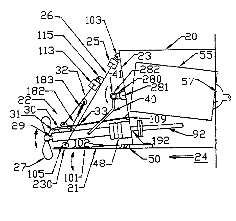
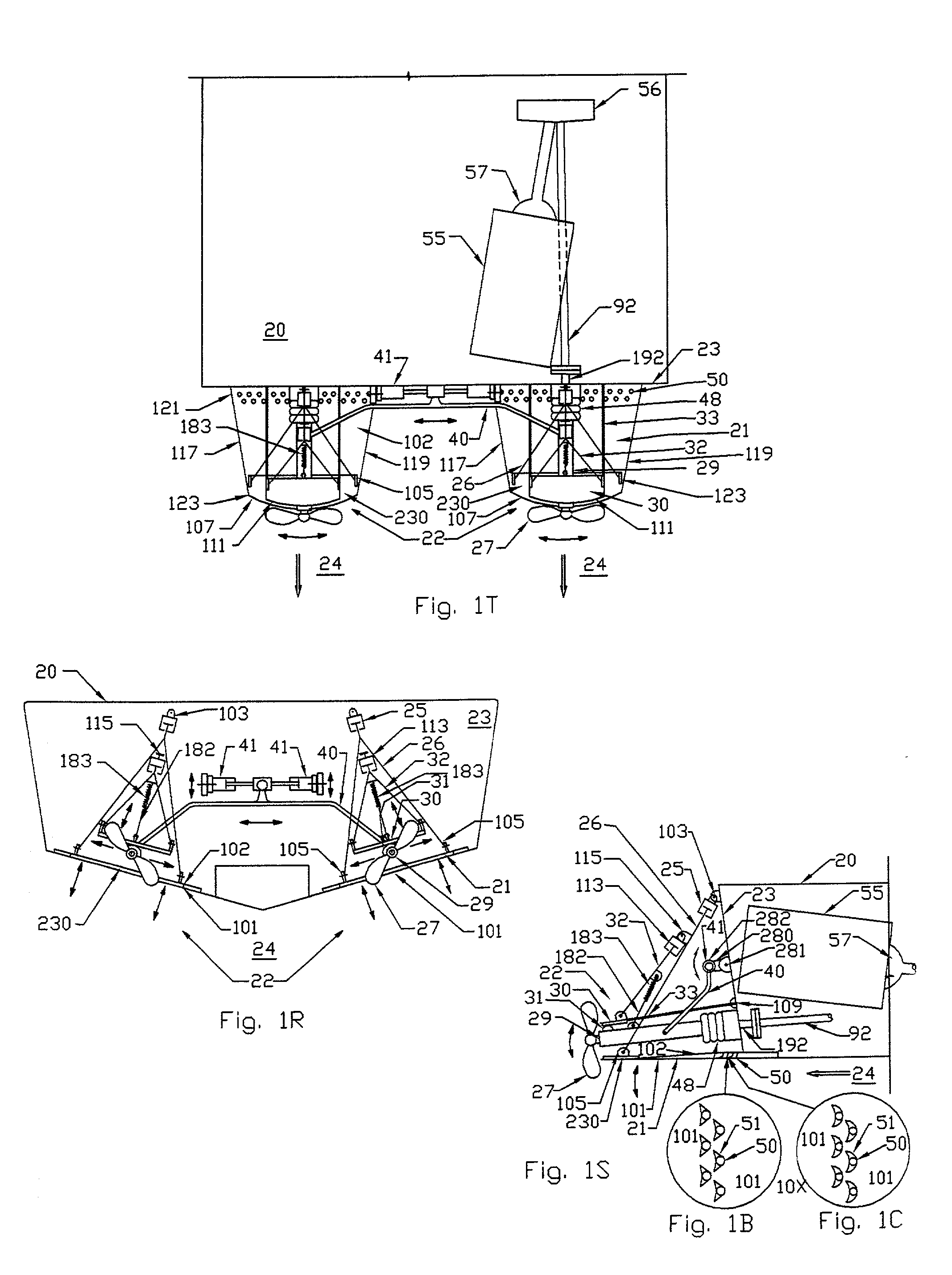
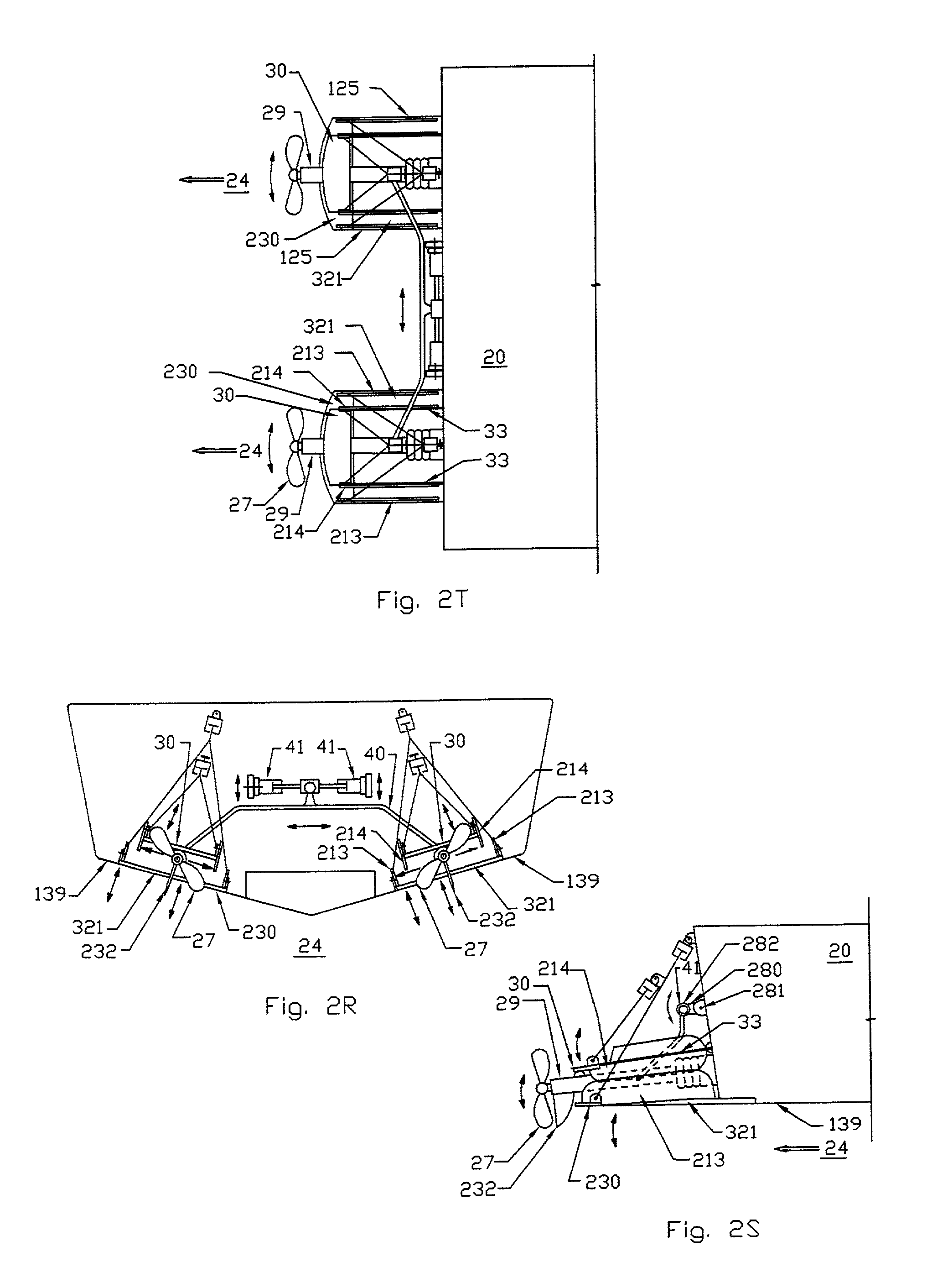
[0073] FIGS. 1S, 1R, and 1T are side (S), rear (R), and top (T) views, respectively, of the stern portion of a boat 20 illustrating an exemplary embodiment of the present invention. It is noted that the reference numeral 20 is used to generally reference each of several boat configurations, such as V-hull boats, flat bottom boats, catamarans, etc., where the particular boat configuration is shown in the Figures and corresponding descriptive text. Also, for simplicity, the description herein often refers to components in the singular, although it is understood that duplicate or complimentary components are often shown or otherwise included, such as, for example, for twin or dual-drive configurations. It is also noted that only the stern portion of the boat, including, in some instances, a transom 23 of the boat, is illustrated as the present invention primarily involves modifications and improvements thereto.

[0074] Attached to the stem of the boat 20 is at least one cantilevered trim...


PUM


Abstract

A trim tab of resilient material affixed in a cantilever fashion at the stern of a boat and of a regressive flexural stiffness such that when deflected, the undersurface of the trim tab assumes the shape of a progressive curve in the direction of water flow. A trim tab of a progressive curve which has gas or liquid ejection to the undersurface to control the boundary layer. A trim tab located under a surface drive whereby the bite of the propeller is controlled relative to the trim tab and the trim tab is controlled to optimize the boat hull.

Description

CROSS-REFERENCE TO RELATED APPLICATION(S)[0001] The present application is based on U.S. Provisional Patent Application entitled "Boat Trim Tabs and Surface Piercing Propeller Drive", Serial No. 60 / 293,618 filed May 25, 2001, which is hereby incorporated by reference in its entirety.[0002] The present invention relates to boating, and more specifically to a trim tab made of resilient material affixed in a cantilever fashion at the stem of a boat and its application to a surface piercing drive propulsion system.DESCRIPTION OF RELATED ART[0003] Trim tabs have been used to change the "attitude" of a boat. Attitude is the angle of the boat relative to the water surface, and changes under different operating conditions. The attitude of a boat relative to the water surface has a profound effect on the speed and efficiency of the boat. Attitude is usually discussed in terms of the nose up / nose down adjustment of the boat, and is sometimes called the trim angle. The term "trim angle" often ...

Claims


Application Information

Patent Timeline
Patent Type & Authority Applications(United States)
IPC IPC(8): B63B1/38B63B39/06B63H5/00B63H5/08B63H5/125B63H20/10B63H20/34
CPCB63B1/38B63B39/061B63H5/00B63H5/08B63H5/125Y02T70/122B63H20/34B63H2001/185B63H2001/286B63H2020/003B63H20/106Y02T70/10
Inventor VON WOLSKE, JAMES P.
Owner VON WOLSKE JAMES P
Learn More