
Fast SAR assessment and certification system for wireless device certification

a wireless device and certification system technology, applied in the direction of measurement devices, material analysis, instruments, etc., can solve the problems of inability to predict the resulting sar profile from design changes, the sar profile of a particular device can depend on unexpectedly and effectively, and the sar profile of a particular device cannot be easily and accurately predicted computationally. , the problem of high cost and large limitations

Inactive Publication Date: 2015-11-10
UNIV OF MARYLAND
View PDF11 Cites 0 Cited by
  • Summary
  • Abstract
  • Description
  • Claims
  • Application Information

AI Technical Summary

Problems solved by technology

Yet, the emission profile or SAR profile of a particular device can depend in unexpected and effectively unpredictable ways on parameters that are readily changed from model generation to generation (e.g., the shape of the device, shape of the antenna, exposure of various device components).
Predicting resulting SAR profiles from design changes is not easily and accurately achieved computationally.
Most, however, are rather cumbersome, expensive and exhibit considerable limitations, including limitations relating to flexibility, reproducibility and speed and ease of use.
While such devices can effectively provide test results, the robotics and other mechanical translation systems can be expensive and difficult to maintain.
Robotics systems and the means to control them with accuracy are inherently expensive.
The mechanical probe system described above is also difficult to calibrate and standardize.
Moreover, techniques relying on the mechanical translation of a probe can be relatively slow and not easily applied to large numbers of test samples.
This limitation provides an upper bound on the speed with which the technique can ascertain the SAR of a particular device in a specific test media.
Such tissue-simulating liquid almost necessarily includes expensive evaporation-resistive chemical additives that can make dealing with the fluid difficult, cumbersome and, in some cases, hazardous.
Readily available, cheaper and more benign alternatives for the phantom fluid are necessarily excluded from use in mechanical probe systems with exposed phantom fluid because of the evaporation problem.
However, these mixtures cannot be used with open phantoms because the alcohol readily causes them to evaporate.
In addition, the nature of the mechanical probe apparatus precludes the use of solid or gelled phantom media.
Current methods involving robotic probes also have physical limitations that can prevent them from being useful for higher frequency tests.
Typical mechanical probes operated by robotics are often too bulky, and their movements too coarse, to provide accurate data in these situations.
Even if a suitable robotics operated mechanical probe were to become available, it would likely be prohibitively expensive.

Method used


Image

  • Fast SAR assessment and certification system for wireless device certification
  • Fast SAR assessment and certification system for wireless device certification
  • Fast SAR assessment and certification system for wireless device certification

Examples


examples

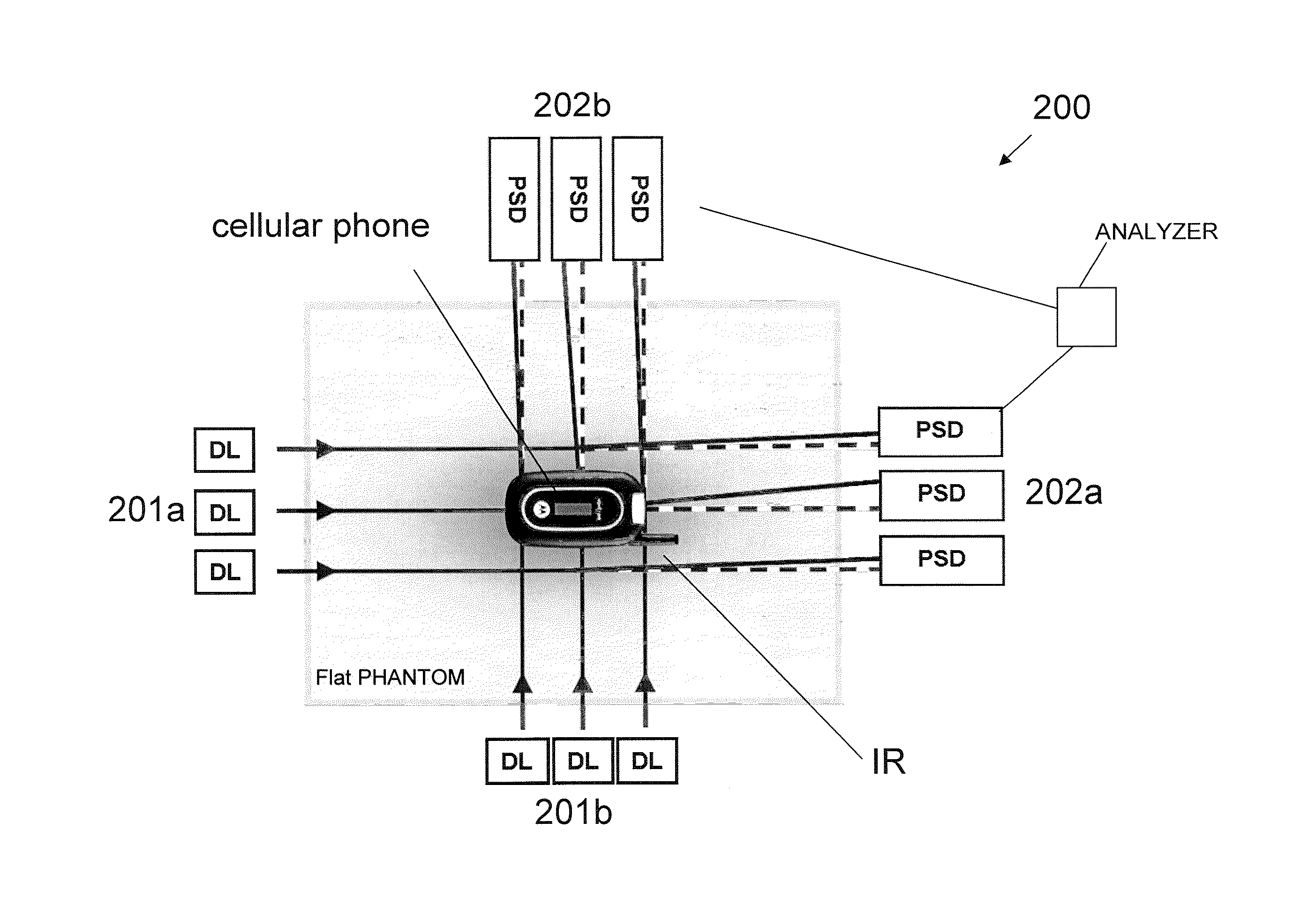
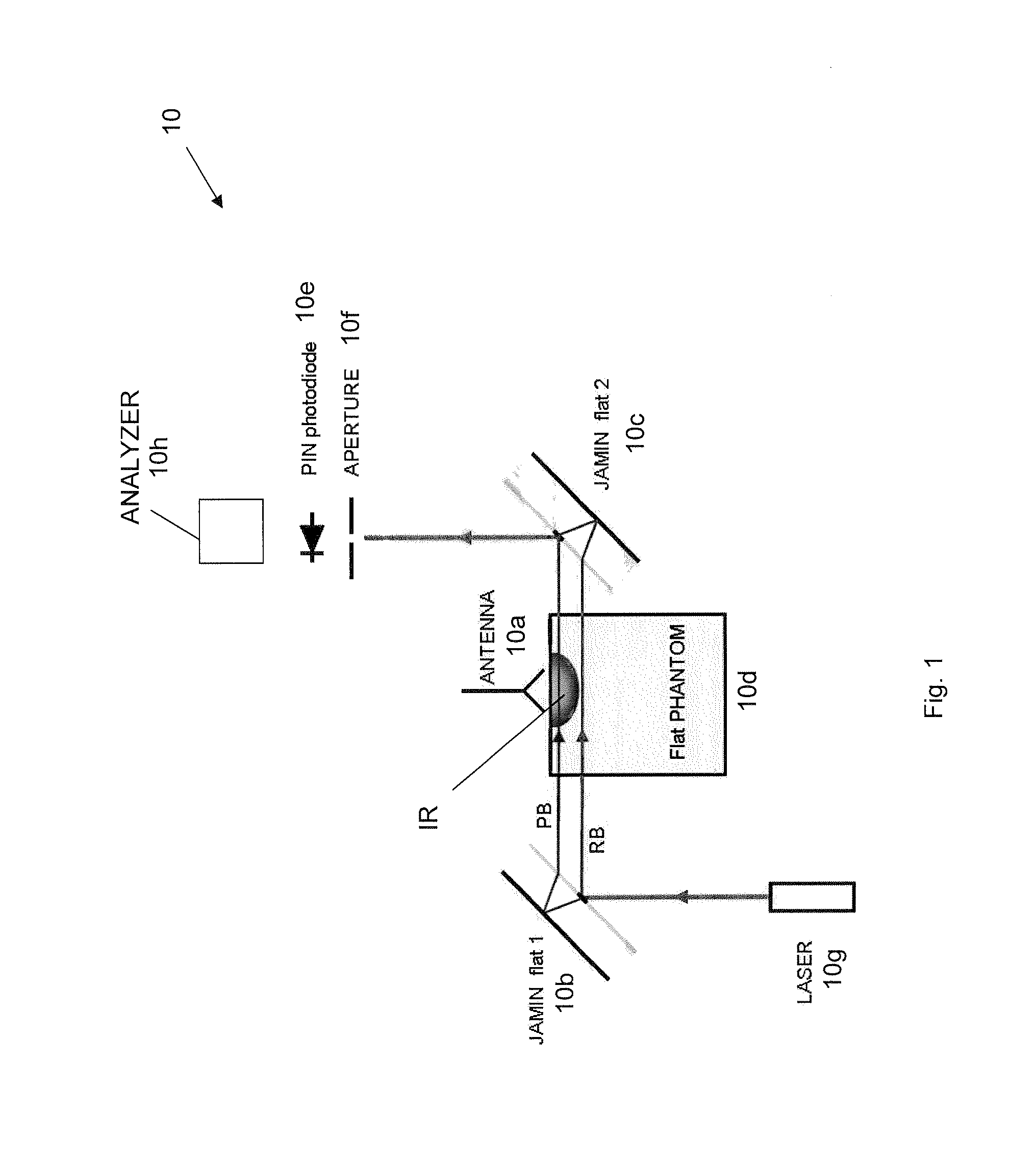
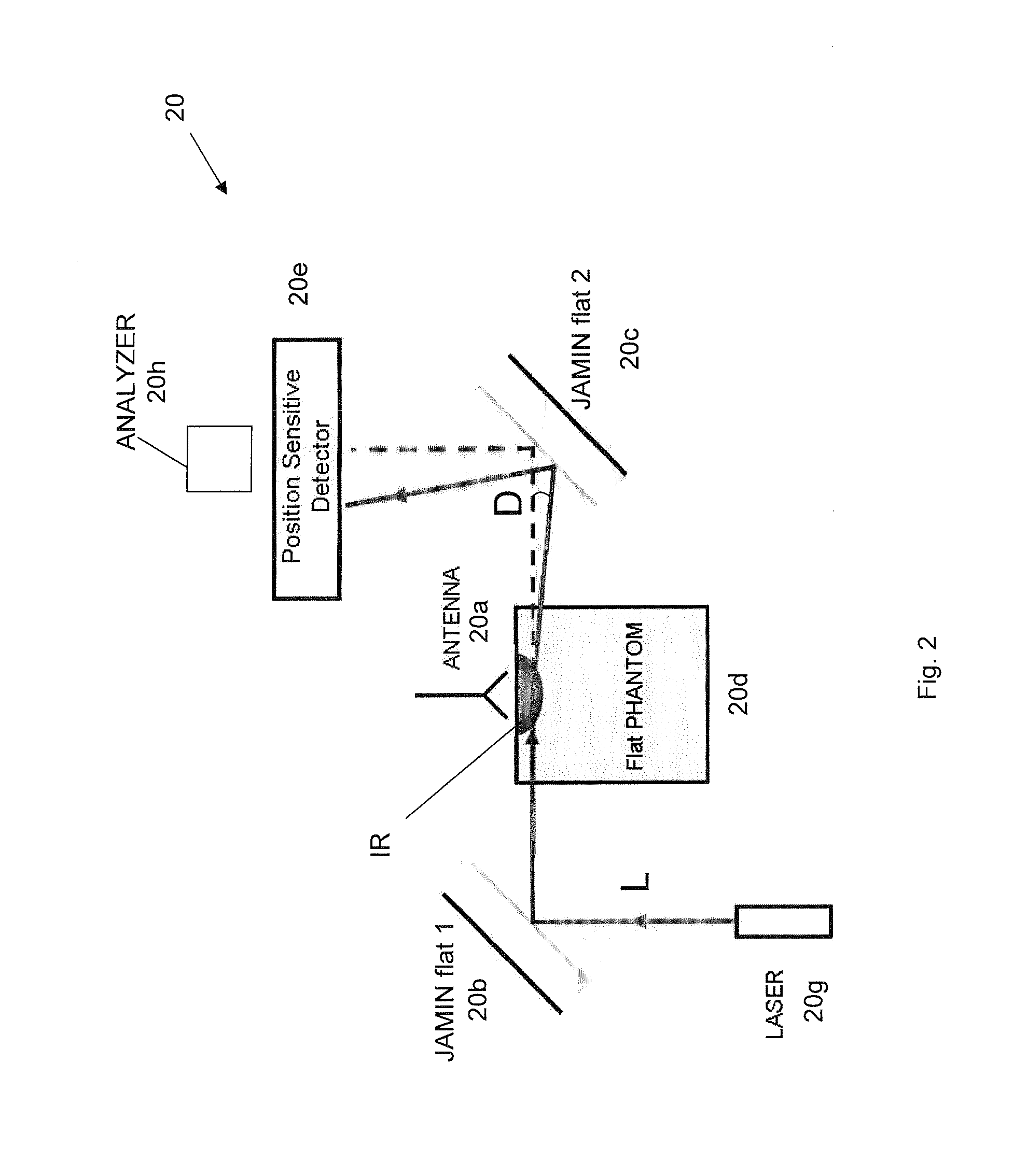
[0071]The following results using variations of the systems described herein demonstrate the use of two complementary optical methods to provide detection of the SAR temperature distribution in various phantoms, in accordance with aspects of the present invention. Either of the techniques may be used independently, or both may be used in tandem. Suitable implementations include their use in an instrument for fast SAR compliance assessment. The examples below demonstrate measurements from the SAR limit of 22.8 mK / min (corresponding to 1.6 W / kg) and above and down to 1.4 mK / min (0.07 W / kg). The results obtained are repeatable to the order of 10% or better. Best results are currently observed within the first minute of exposure time, although measurement time can be shortened or lengthened as needed.

[0072]As shown in the results described further below, the system 100 of FIG. 3 was tested at 900 and 1800 MHz. It is to be understood, however, that the system may work at even higher freq...


PUM


Abstract

A new rapid optical specific absorption rate (SAR) system is disclosed. The rapid optical SAR system has ability to measure and map the power deposited in a flat phantom or other phantom filled with a transparent simulant fluid. Absolute rates of temperature increase in the phantom by photo thermal techniques are measured. For example, the temperature increase and gradients in the phantom bend the path of a laser beam, which may be aimed at a position sensitive detector. The spatial SAR may be mapped and SAR differences between different telephones and telephone orientations, for example, can be distinguished. The system is non-invasive and non-perturbing of the SAR distribution in the phantom, can measure at locations up to the interior surface of the phantom, and provides thermally-based SAR measurements that do not necessarily require constant calibration.

Description

[0001]This application claims priority to Applicant's U.S. Provisional Patent Appl. No. 61 / 060,307 titled “RAPID SAR ASESSMENT SYSTEM” filed Jun. 10, 2008, the entirety of which is incorporated herein by reference.BACKGROUND OF THE INVENTION[0002]1. Field of the Invention[0003]Aspects of the present invention relate to devices and systems for measuring the specific absorption rate (SAR) for wireless and other electromagnetic radiation emitting devices. Aspects of the present invention also relate to techniques for measuring SAR or thermal effects generally. One aspect of the present invention relates to an optical technique for measuring SAR for wireless and other electromagnetic radiation emitting devices.[0004]2. Background of the Related Art[0005]The Federal Communications Commission (FCC) sets guidelines for the acceptable levels of electromagnetic radiation emitted by various wireless devices used in close proximity to the human body. Similar standards are applied globally. Dev...

Claims


Application Information

Patent Timeline
Patent Type & Authority Patents(United States)
IPC IPC(8): G01B9/02G01R29/08
CPCG01R29/0885G01R29/0857
Inventor DAVIS, CHRISTOPER C.BALZANO, QUIRINOHODZIC, VILDANAGAMMON, ROBERT W.
Owner UNIV OF MARYLAND
Learn More