Flange system with modular spacers

a modular spacer and flange technology, applied in the direction of pipe connection arrangements, water closets, mechanical devices, etc., can solve the problems of insufficient flexibility, inability to allow any non-, inconvenient installation, etc., and achieve the effect of preventing kinking of the flexible sleeve and sufficient flexibility

Active Publication Date: 2015-11-17
COFLEX SA DE CV
View PDF35 Cites 7 Cited by
  • Summary
  • Abstract
  • Description
  • Claims
  • Application Information

AI Technical Summary

Benefits of technology

[0009]The present disclosure generally relates to improved water closet flanges and methods for installing such water closet flanges. In an exemplary embodiment, an improved water closet flange apparatus includes an outer flange and a plurality of modular spacers operable to raise an upper surface of the outer flange so that the upper surface is disposed above a finish flooring surface located on top of a ground slab. The modular spacers have a plurality of projections extending from their upper surface to be received into recessed areas defined in the lower surface of the outer flange. Furthermore, the modular spacers are stackable. In one embodiment, the apparatus also includes a flexible conduit portion (i.e. sleeve) extending downwardly from the outer flange. The flexible sleeve has a sufficient degree of flexibility to accommodate connection between offset, misaligned, angled, or otherwise incongruous plumbing fixture discharges and waste drainpipe outlets. In one embodiment, the flexible sleeve includes at least one corrugated portion to aid the desired flexibility while preventing kinking of the flexible sleeve. An upper portion of the flexible sleeve may include an inwardly extending lip portion to accommodate the desired seal between the plumbing fixture discharge and the flange apparatus, thereby eliminating the need for a separate gasket element, such as a wax seal or rubber foam seal. Also, the improved water closet flange connects plumbing fixture discharges and waste drainpipes without any flow reduction between such elements.

Problems solved by technology

Accordingly, such water closet flanges are formed to be rigid and generally do not provide any kind of flexibility along their conduit portion and are therefore insufficient for allowing any non-negligible distortion of the flange.
As can be appreciated, the aforementioned problems are attributable to varying construction methods and materials.
However, these solutions are not reliable because the seal connection is not strong enough to prevent leakage and associated odors, and oftentimes they can be expensive and inefficient due to delays in the installation process.
Also, conventional closet flanges are made for a specific type of piping, such as cast iron piping, PVC piping, or ABS piping, but not compatible with multiple types of pipings.

Method used


Image

  • Flange system with modular spacers
  • Flange system with modular spacers
  • Flange system with modular spacers

Examples


Embodiment Construction

[0037]Various aspects of a flexible flange apparatus and related methods for installing a flexible flange apparatus according to the present disclosure are described. It is to be understood, however, that the following explanation is merely exemplary in describing the devices and methods of the present disclosure. Accordingly, several modifications, changes and substitutions are contemplated.

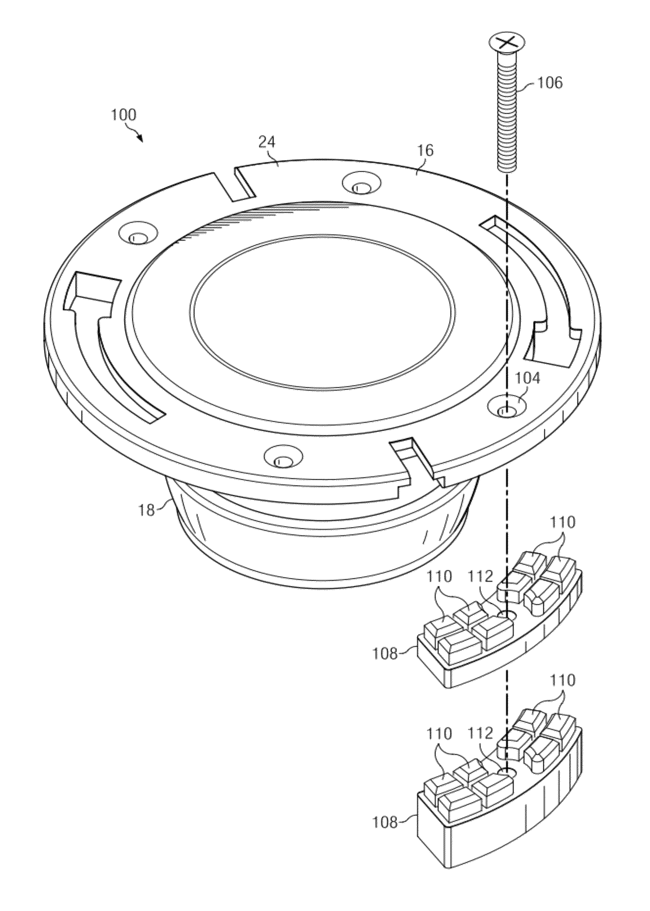
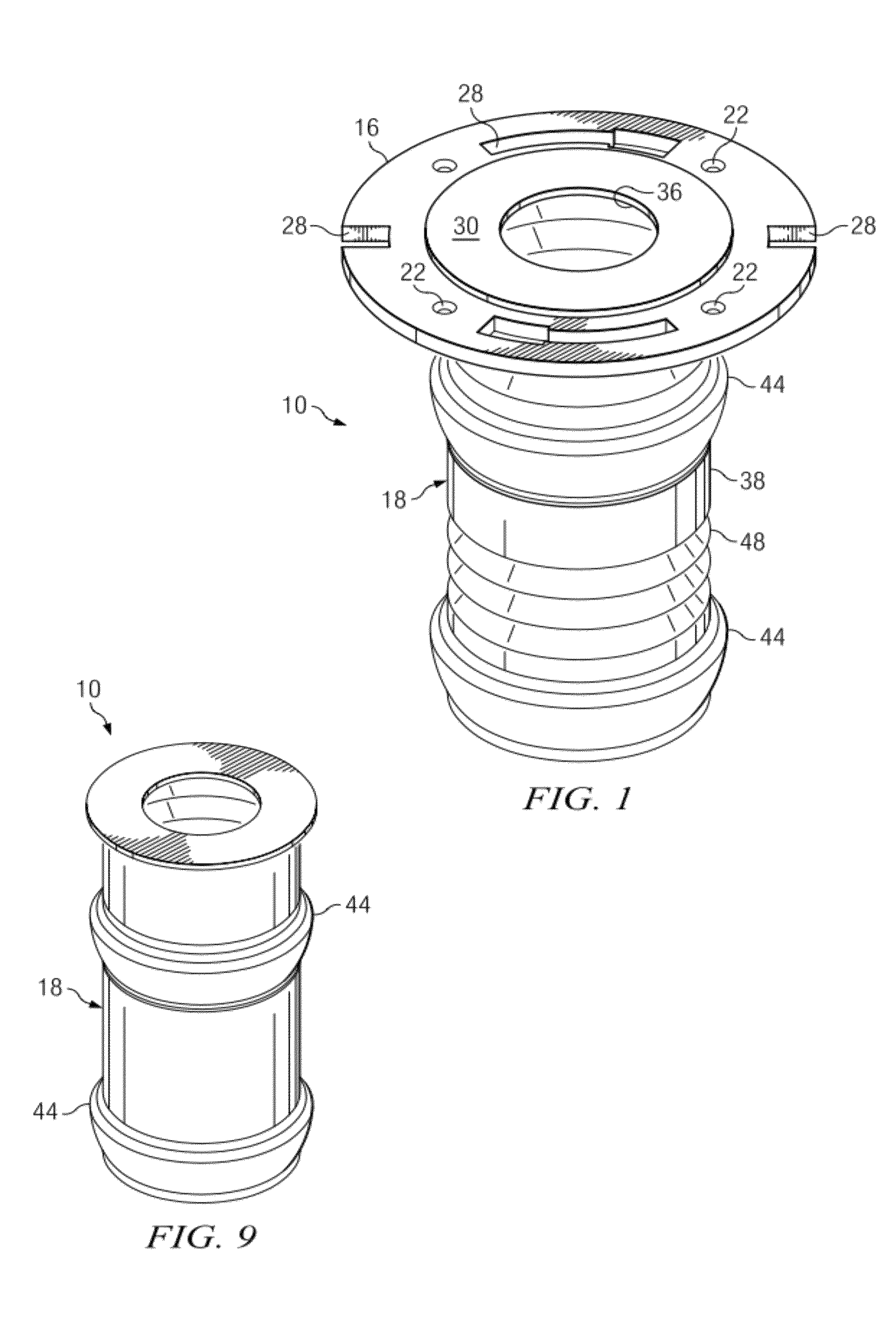
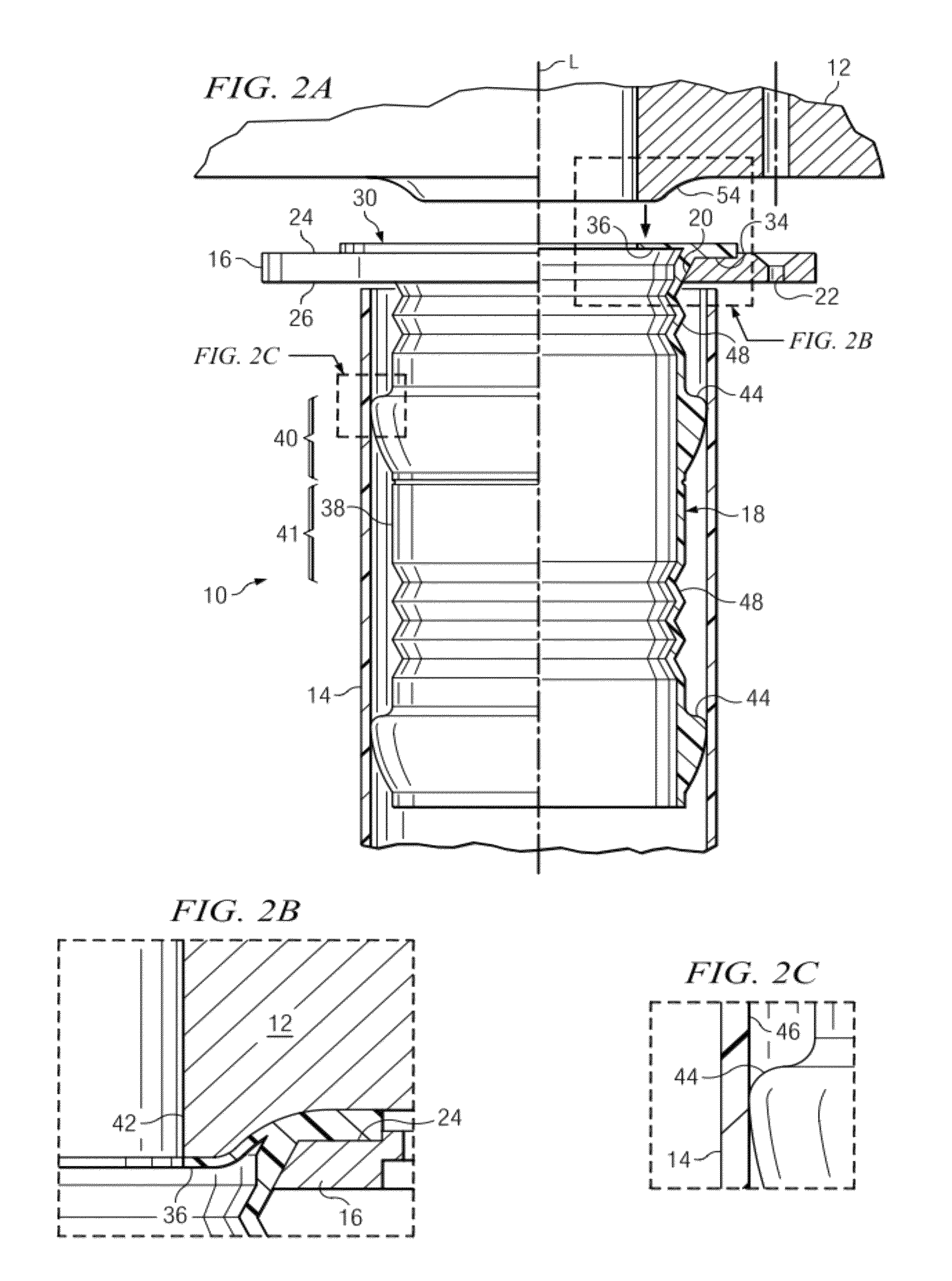
[0038]FIGS. 1 and 2A illustrate a flexible flange apparatus 10 for connecting between a plumbing fixture discharge 12 and a waste drainpipe outlet 14. The flange apparatus includes an outer flange 16 and a sleeve 18 disposed through an aperture 20 of the outer flange. In some embodiments, the sleeve 18 is integrally formed with the outer flange 16 as a single piece, while in other embodiments, the sleeve is removably seated on the outer flange. The outer flange 16 may include one or more apertures 22 formed through the outer flange from an upper surface 24 to a lower surface 26 of the outer flan...


PUM

PropertyMeasurementUnit
angle of deflectionaaaaaaaaaa
lengthaaaaaaaaaa
angle of deflectionaaaaaaaaaa

Abstract

The present disclosure generally relates to improved water closet flanges and methods for installing such water closet flanges. In one exemplary embodiment, an improved water close flange apparatus includes a modular spacer system for raising an upper surface of the outer surface above a finish flooring surface installed on top of a ground slab in order to improve the ease of installation. In one embodiment, an improved water closet flange apparatus includes an outer flange and a flexible conduit portion (i.e. sleeve) extending downwardly therefrom. The flexible sleeve has a sufficient degree of flexibility to accommodate connection between offset, misaligned, angled, or otherwise incongruous plumbing fixture discharges and waste drain pipe outlets. In one embodiment, the flexible sleeve includes at least one corrugated portion to aid the desired flexibility. An upper portion of the flexible sleeve may include an inwardly extending lip portion to accommodate the desired seal between the plumbing fixture discharge and the flange apparatus. Related methods for installing the disclosed flange apparatus between plumbing fixture discharges and waste drainpipes are also described. Embodiments of flange systems with modular spacers are also disclosed.

Description

CROSS-REFERENCE TO RELATED APPLICATIONS[0001]The present application is a continuation-in-part of the co-pending U.S. patent application Ser. No. 12 / 906,947 filed on Oct. 18, 2010, which is a continuation application of U.S. patent application Ser. No. 11 / 212,091 filed on Aug. 25, 2005, now U.S. Pat. No. 7,814,580, issued Oct. 19, 2010, entitled “Flexible Flange Apparatus For Connecting Conduits and Methods for Connecting the Same,” which is a continuation-in-part of U.S. patent application Ser. No. 10 / 370,747, filed Feb. 20, 2003, entitled “Improved Flexible Sleeve for Connection to a Plumbing Fixture,” all of which are incorporated herein by reference in their entirety.TECHNICAL FIELD[0002]The present disclosure relates generally to devices for connecting conduits, such as plumbing fixtures to waste drain conduits, and more particularly to a flange apparatus, including a specially configured flexible sleeve and a closet flange, which mounts a water closet (toilet) on a supporting ...

Claims


Application Information

Patent Timeline
Patent Type & Authority Patents(United States)
IPC IPC(8): E03D11/16F16L47/14F16L47/06F16L47/18F16L47/32E03D11/17
CPCE03D11/16F16L47/06F16L47/14F16L47/18F16L47/32E03D11/17Y10T29/49826
Inventor CORONADO, EDUARDOSADA, JORGE
Owner COFLEX SA DE CV
Why Eureka
Try Eureka