Computer-implemented method for drawing a polyline in a three-dimensional scene

a three-dimensional scene and polyline technology, applied in the field of computer graphics, can solve the problems of inability to accurately determine the angle between segments of consecutive segments of polyline, cumbersome grid creation and positioning, and loss of user experience, so as to achieve the effect of sufficient flexibility, simple and effective, and accurate determination of the angle between segments

Active Publication Date: 2020-07-14
DASSAULT SYSTEMES
View PDF7 Cites 0 Cited by
  • Summary
  • Abstract
  • Description
  • Claims
  • Application Information

AI Technical Summary

Benefits of technology

[0008]The invention aims at overcoming these drawbacks of the prior art. More specifically the invention aims at providing a simple and effective method for drawing polylines in a three-dimensional scene, with a sufficient degree of flexibility and yet allowing an accurate determination of the angles between segments of the polyline.
[0009]According to the invention, this aim is achieved by the use of a particular graphical tool, which may be called a “plane selector”. This tool is displayed for the first time after the drawing of a first segment; it allows the user to select a plane parallel or perpendicular to this segment, then creates a grid “on the fly” on the selected plane to ease the drawing of the successive segment, and so on. This way the user can draw the polyline step by step, choosing the positioning on the breakings and (with some constraints) the angles formed by the different segments, while being relieved from the burden of manually positioning the drawing grids.

Problems solved by technology

The angle between consecutive segments of the polyline may not take accurate values (e.g. 45° or 90°); most importantly, as the polyline is not properly situated in three-dimensions, they are lost if the user changes the point of view.
A drawback of this technique is that it is quite cumbersome to create and position a grid before drawing each segment.
Also, drawing a complex three-dimensional polyline requires the simultaneous display of several grids, which may be confusing for the user and demanding (essentially in terms of memory space) for the Computer Aided Design / illustration authoring system.
This approach is not flexible enough, as the user has no control on the position of the “breakings” of the line.
The result is often unsatisfactory for a human end user, as depicted on FIG. 4.

Method used


Image

  • Computer-implemented method for drawing a polyline in a three-dimensional scene
  • Computer-implemented method for drawing a polyline in a three-dimensional scene
  • Computer-implemented method for drawing a polyline in a three-dimensional scene

Examples


Embodiment Construction

[0037]A description of example embodiments of the invention follows.

[0038]Hereafter, a “three-dimensional” (or “3D”) object will be an object, or rather its digital representation in a computer system, allowing a three-dimensional (3D) graphical representation. A 3D representation allows the viewing of the part from all angles. For example, a 3D object, when 3D represented, may be handled and turned around any of its axes, or around any axis in the screen on which the representation is displayed. A three-dimensional scene is constituted by a plurality of 3D objects disposed in a three-dimensional space.

[0039]Conversely, a “two-dimensional” (or “2D”) object will be an object only allowing a two-dimensional (2D) representation e.g. on a plane. For example, a 2D object may only be translated in the plane of the screen on which the representation is displayed, or rotated around an axis perpendicular to said screen.

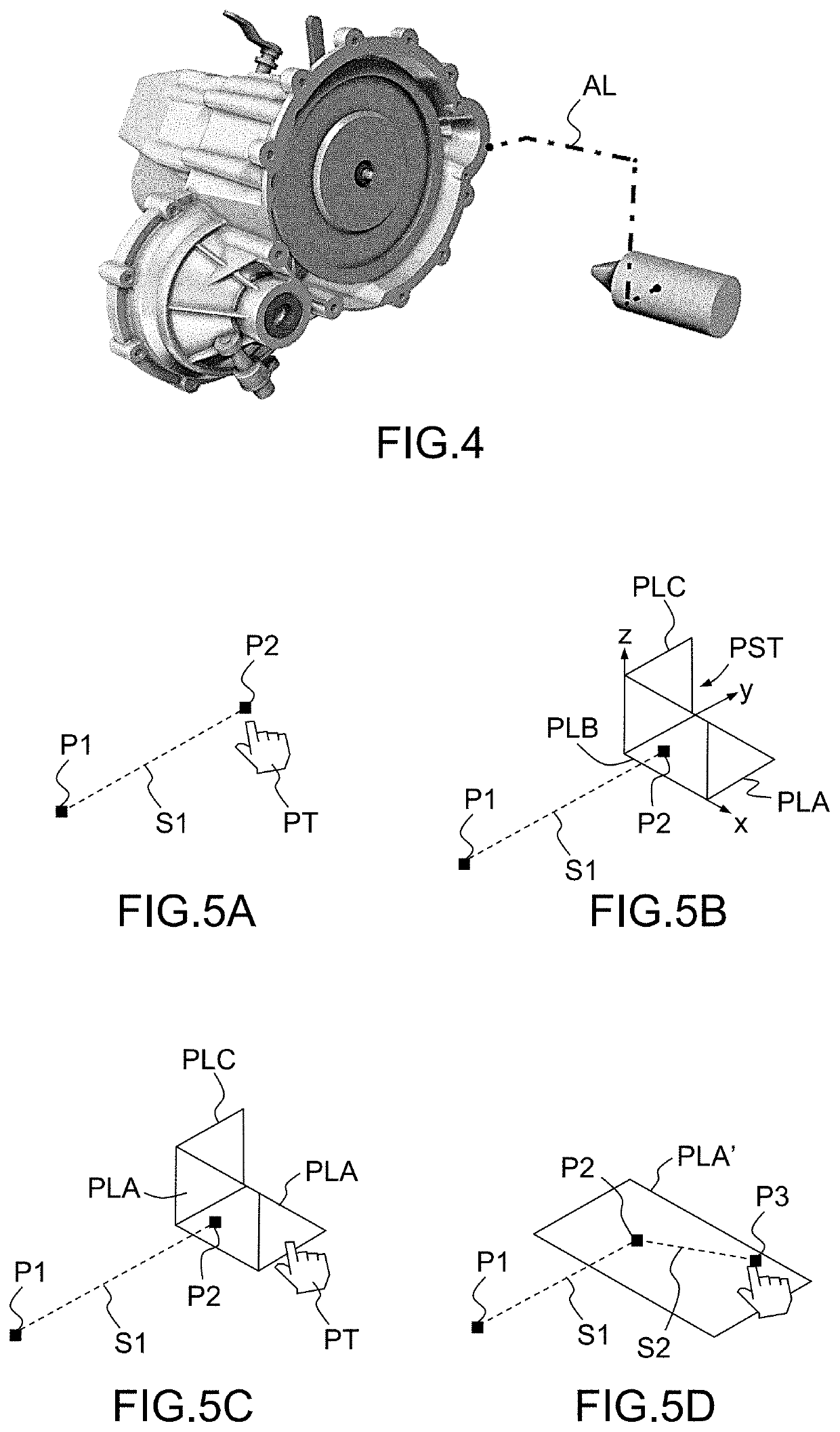
[0040]The first step of the inventive method, illustrated on FIG. 5A, con...


PUM


Abstract

A computer-implemented method of drawing a polyline in a three-dimensional scene: a) draws a segment (S1) of said polyline in said three-dimensional scene, said segment having a starting point (P1) and an endpoint (P2); b) displays, in the three-dimensional scene, a graphical tool (PST) representing a set of three orthogonal planes (PLA, PLB, PLC), one of said planes being orthogonal to the segment; c) selects one of said planes; and d) draws another segment of the polyline (S2), having a starting point coinciding with the endpoint of the segment drawn in step a) and lying in the plane (PLA) selected in step c). Steps a), c) and d) are carried out based on input commands provided by a user. A computer program product, non-volatile computer-readable data-storage medium and Computer Aided Design or three-dimensional illustration authoring system carries out such a method.

Description

RELATED APPLICATION(S)[0001]This application claims priority under 35 U.S.C. § 119 or 365 to Europe, Application No. 15306956.2, filed Dec. 8, 2015. The entire teachings of the above application(s) are incorporated herein by reference.FIELD OF THE INVENTION[0002]The invention relates to a computer-implemented method for drawing a polyline, i.e. a broken line, in a three-dimensional (3D) scene. The polyline may, in particular, be an assembly path, i.e. a polyline used to illustrate how the elements of a system, shown in an exploded view, are assembled.[0003]The invention applies to the field of computer graphics, and more particularly to the field of Computer Aided Design (CAD) and illustration authoring. The invention is particularly suitable for producing technical illustrations, marketing presentations, assembly illustrations, training materials etc.BACKGROUND[0004]In all the applications above, there is a need of creating exploded views of assemblies or sub-assemblies, to illustr...

Claims


Application Information

Patent Timeline
Patent Type & Authority Patents(United States)
IPC IPC(8): G06T11/20G06T3/40G06T3/00G06F30/00G06T19/20
CPCG06T19/20G06T11/203G06T3/0081G06T3/40G06F30/00G06T2200/24G06T2219/2004G06T2219/016G06T2207/20092G06T19/00G06F30/20
Inventor DELFINO, CHRISTOPHE RENE FRANCISARQUES, NICOLAS
Owner DASSAULT SYSTEMES
Why Eureka
Try Eureka