
Bulletproof protection structure and corresponding bulletproof vest

a protection structure and bulletproof technology, applied in the field of bulletproof protection structures, can solve the problems of affecting complicating the protection of surfaces, imposition of square forms with corner edges, etc., and achieve the effect of increasing the protection level and degree of flexibility

Active Publication Date: 2019-11-12
ELET CA S R L CON SOCIO UNICO
View PDF21 Cites 1 Cited by
  • Summary
  • Abstract
  • Description
  • Claims
  • Application Information

AI Technical Summary

Benefits of technology

This patent is about a new bulletproof protection structure that is flexible enough to cover irregular surfaces, like those of a bulletproof vest. It also increases the level of protection up to high calibers like those of AK47 rifles and M2AP ammunition. The structure uses a ballistic panel made up of many small, independent elements to provide flexibility. This invention solves the limitations of previous structures.

Problems solved by technology

It is emphasized that the impact of bullets on this ballistic panel may in any case result in impact traumas.
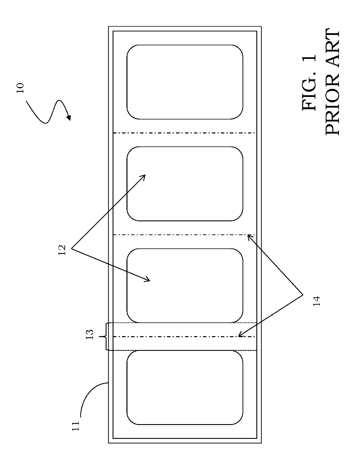
This complicates the protection of surfaces which are irregular and makes protection practically impossible in the case of rounded forms, such as cylindrical towers, leading to the imposition of square forms with corner edges.
This problem becomes even greater in the case of personal protective clothing which can be worn by a user, such as a bulletproof vest or jacket, in particular suitable for effective bulletproof protection against calibers greater than 0.357 and 0.44 Magnum, namely higher than a level IIIa of the United States NIJ standard.
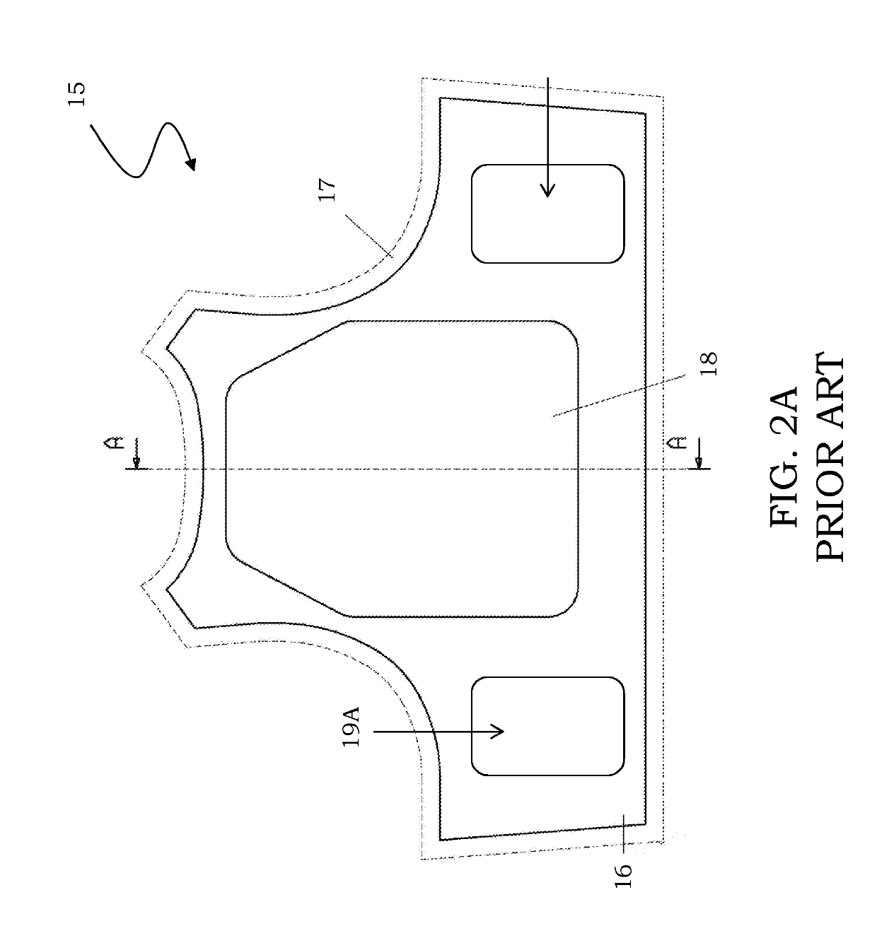
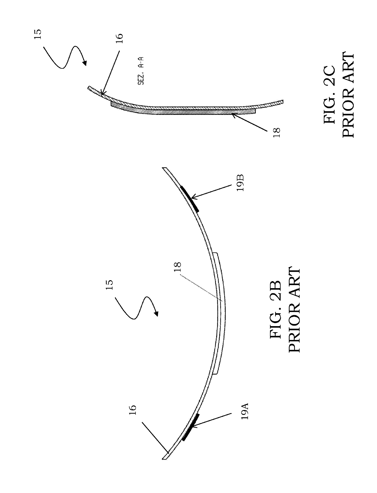
Obviously these ballistic panels constitute an impediment to the movement of the human body, limiting the freedom of movement of the user wearing the bulletproof vest 15.
Another drawback resulting from the ballistic panels is also the weight of the bulletproof vest 15, this being a very constraining factor when choosing the protection which is most suitable for the missions to be carried out.
The known solutions, although advantageous under many respects, therefore have various drawbacks, including the difficulty of adapting the bulletproof protection structures for calibers greater than 0.357 and 0.44 Magnum, namely higher than a level IIIa of the United States NIJ standard, to surfaces which are not flat.
Moreover, in the case of garments for bulletproof protection of persons, the use of ballistic reinforcing panels results in the extreme rigidity and additional weight of the garments, which limit the comfort of the person wearing them; moreover they are able to provide effective protection only for an area substantially limited to the zones of the vital organs, such as the heart, owing to at least one ballistic panel positioned over the chest of the user wearing the vest.

Method used


Image

  • Bulletproof protection structure and corresponding bulletproof vest
  • Bulletproof protection structure and corresponding bulletproof vest
  • Bulletproof protection structure and corresponding bulletproof vest

Examples


Embodiment Construction

[0055]Referring to the figures, a bulletproof protection structure, being illustrated schematically in FIG. 3A and denoted overall by 20, is described. The bulletproof protection structure 20 is in particular of the type suitable for ensuring effective bulletproof protection for calibers greater than 0.357 and 0.44 Magnum, namely higher than a level IIIa of the United States NU standard.

[0056]It should be pointed out that the figures show schematic views and are not drawn to scale, but are instead drawn so as to emphasize the main characteristic features of the invention. Moreover, in these figures, the different components are also shown in schematic form, whereby their form may vary depending on the desired application.

[0057]Moreover, the following discussion is presented to enable a person skilled in the art to make and use the invention. Various modifications to the embodiments will be readily apparent to those skilled in the art, and the generic principles herein may be applied...


PUM

PropertyMeasurementUnit
lengthaaaaaaaaaa
lengthaaaaaaaaaa
speedaaaaaaaaaa

Abstract

A bulletproof protection structure comprises at least a flexible base and a reinforcing structure realized by means of at least one ballistic panel associated with the flexible base. The ballistic panel is finely divided into a plurality of elementary components, individually associated with the flexible base, structurally independent of one another and not bound to each other, so as to ensure flexibility for the structure as a whole.

Description

FIELD OF THE INVENTION[0001]The present disclosure relates to a bulletproof protection structure.[0002]The disclosure relates, in particular, but not exclusively, to a protection structure suitable for making bulletproof vests able to ensure high levels of protection, in particular higher than a IIIa of the United States NIJ standard, and the description which follows is made with reference to this field of application with the sole object of simplifying the illustration thereof.BACKGROUND OF THE INVENTION[0003]It is known to obtain effective bulletproof protection thanks to structures which are realized by means of suitable combinations of interwoven fibers able to absorb and disperse the stopping force and penetration of the bullets by means of plastic deformation (elongation) of said fibers.[0004]The number of superimposed layers determines the protective capacity of the structure as a whole, which is categorized for example in protection classes referred to as NIJ (United States...

Claims


Application Information

Patent Timeline
Patent Type & Authority Patents(United States)
IPC IPC(8): A41H1/00F41H1/02F41H5/04B32B3/16B32B5/02B32B9/00
CPCF41H1/02B32B9/005F41H5/0492B32B3/16B32B5/024B32B2437/00B32B2260/00B32B2262/0253B32B2571/02B32B2307/558
Inventor CONTRI, ALBERTO
Owner ELET CA S R L CON SOCIO UNICO
Learn More