Supercharge Your Innovation With Domain-Expert AI Agents!

Separator and separation method

a separation method and separator technology, applied in the field of devices and separation methods, can solve problems such as maintenance problems, water contamination and environment pollution, and disadvantages in terms of cost, and achieve the effects of enhancing the processing performance of separation, avoiding maintenance problems, and avoiding clogging

Active Publication Date: 2015-11-17
HANEX CO LTD
View PDF59 Cites 1 Cited by
  • Summary
  • Abstract
  • Description
  • Claims
  • Application Information

AI Technical Summary

Benefits of technology

The vertical swirling flow design prevents clogging by allowing solids to be easily swept off the screen, and the wedge wire screen configuration enables efficient separation of fine solids while maintaining high liquid passage efficiency, reducing maintenance needs and installation complexity.

Problems solved by technology

Solids such as sediment, a variety of garbage, papers, and fallen leaves are mixed in the rainwater drainage flowing in the sewerage system after dropping onto the ground surface and flowing on the ground surface, and if those solids are discharged to the rivers, they will cause water contamination; if they flow into the rainwater storing-infiltrating facilities, it will become necessary to frequently perform maintenance of the facilities; therefore, they will cause disadvantage in terms of cost.
Furthermore, rainwater is temporarily stored underground without removal of solids in a rainwater storage tank or the like for flood countermeasures against torrential rain, and the stored rainwater needs to be pumped up during fine weather to be discharged to a river; on that occasion, however, the solids are also simultaneously discharged to the river, so as to cause the river water contamination and environment pollution problem.
It is common practice to use a screen or a filter as a device for separating and removing the solids in drainage water, but they are likely to be clogged by solids, to cause a maintenance problem thereof.
However, while the separator permits easy maintenance because of no use of the filter or screen, it is difficult for the separator to perform secure separation and capture of floating and fine solids of size to be removed.

Method used


Image

  • Separator and separation method
  • Separator and separation method
  • Separator and separation method

Examples


embodiment 1

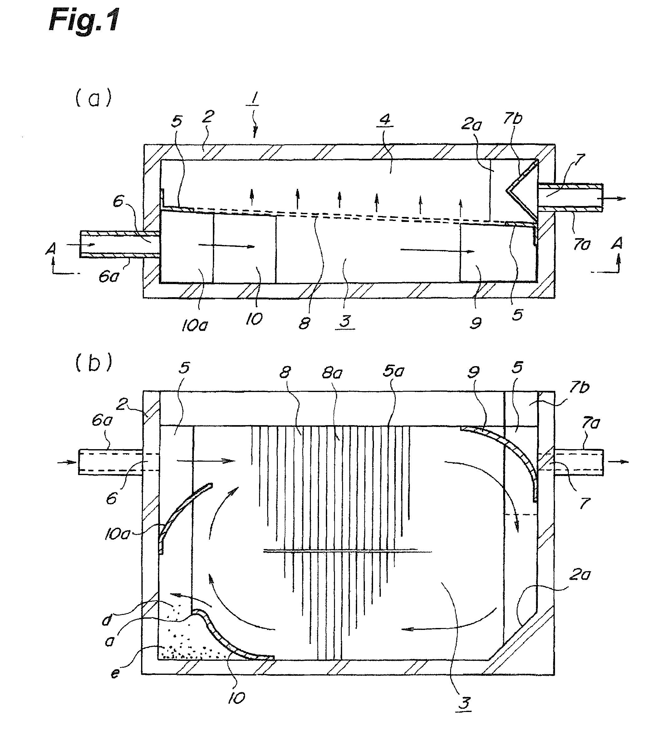
[0094]FIG. 1 shows the first embodiment of the separator according to the present invention, wherein (a) is a plan view and (b) is an A-A cross-sectional view of (a). The separator 1 has a separation tank 2, a partition plate 5 partitioning an inside space of the separation tank 2 into an inflow chamber 3 and an outflow chamber 4, a liquid inlet 6 formed at an upper part of the inflow chamber 3, and a discharge outlet 7 formed at an upper part of the outflow chamber 4, and the partition plate 5 is provided with a screen 8. The screen 8 may be attached directly to the peripheral wall part of the separation tank 2, without providing the partition plate 5, and in that case, the screen 8 also serves as the partition plate 5.

[0095]The separation tank 2 shown in FIG. 1 is formed with a plane cross section of a rectangular shape having a longitudinal axis and a transverse axis, but the plane cross section may be an elliptical shape or a rectangular-circular shape rectangular on the liquid ...

embodiment 2

[0114]FIG. 2 shows the second embodiment of the separator according to the present invention, wherein (a) is a plan view and (b) a B-B cross-sectional view of (a). The separator 1 of the second embodiment is different from the example of FIG. 1 in that two screens 8 are used and downstream ends of the two screens 8 are coupled to each other through the guide 9, and the other part is configured in the same manner as in the example of FIG. 1. Therefore, the same portions as those in FIG. 1 are denoted by the same reference symbols in FIG. 2, and redundant description is omitted herein.

[0115]The guide 9 in the second embodiment, as shown in FIG. 2(b), is composed of a U-shaped plate with a vertical cross section of an arcuate shape and side plates closing two sides thereof, and one ends of the respective partition plates 5 are coupled thereto along its vertical edges. The guide 9 in the present embodiment also serves as a part of the partition plates 5. The two partition plates 5 are a...

embodiment 3

[0118]FIG. 3 shows the third embodiment of the separator according to the present invention, wherein (a) is a plan view and (b) a C-C cross-sectional view of (a). The separator 1 of the third embodiment is a modification example of the embodiment of FIG. 2 and is different in the following three points from the example of FIG. 2: the two partition plates 5 are arranged so that they are parallel to each other from the liquid inlet 6 toward the downstream side; thus the two screens 8 provided at the respective partition plates 5 are also arranged so that they are parallel to each other from the liquid inlet 6 toward the downstream side; and a guide body 11 comprised of a plate member of a rectangular shape extending horizontally is provided in the middle part of the inflow chamber 3; the other part is configured in the same manner as in the example of FIG. 2. Therefore, the same portions as those in FIG. 2 are denoted by the same reference signs, and redundant description is omitted h...


PUM

PropertyMeasurementUnit
particle diameteraaaaaaaaaa
average particle diameteraaaaaaaaaa
widthaaaaaaaaaa

Abstract

A problem is to solve problems on removal of solids by a screen and on an installation space and pipe connection in a separator. A solution to the problem is as follows. A separator 1, which is a device for separating solids contained in influent liquid, has a separation tank 2; a partition plate 5 partitioning an inside space of the separation tank 2 into an inflow chamber 3 and an outflow chamber 4; a screen 8 provided at the partition plate 5; a liquid inlet 6 formed at the inflow chamber 3; and a discharge outlet 7 formed at the outflow chamber 4; the inflow chamber 3 is provided with a guide unit 9, 10, 10a for forming a vertical swirling flow in the inflow chamber 3 by reversing the influent liquid from the liquid inlet 6; the screen 8 is disposed along a side face of the swirling flow thus formed. This configuration permits the solids to be removed, without clogging the screen with the solids.

Description

TECHNICAL FIELD[0001]The present invention relates to a device and separation method for separating solids contained in drainage water flowing through sewerage pipes or in liquid circulating through an in-plant wastewater treatment facility or the like.BACKGROUND ART[0002]Of drainage water such as rainwater flowing into a sewerage system laid in an urban area, part is stored in or discharged into the earth by facilities for storing or infiltrating rainwater, while the rest is discharged to rivers. Solids such as sediment, a variety of garbage, papers, and fallen leaves are mixed in the rainwater drainage flowing in the sewerage system after dropping onto the ground surface and flowing on the ground surface, and if those solids are discharged to the rivers, they will cause water contamination; if they flow into the rainwater storing-infiltrating facilities, it will become necessary to frequently perform maintenance of the facilities; therefore, they will cause disadvantage in terms o...

Claims


Application Information

Patent Timeline
Patent Type & Authority Patents(United States)
IPC IPC(8): B01D29/01E03F5/14B01D29/03B01D29/31
CPCE03F5/14B01D29/03B01D29/31B01D29/445B01D29/906B01D2201/02
Inventor SEMBA, FUJIOOHHIRA, SATOSHISHIOYA, TAKUOTSUNODA, ATSUSHI
Owner HANEX CO LTD
Features
  • R&D
  • Intellectual Property
  • Life Sciences
  • Materials
  • Tech Scout
  • Unparalleled Data Quality
  • Higher Quality Content
  • 60% Fewer Hallucinations
Learn More