Integrated circuit power management

a power management and integrated circuit technology, applied in pulse generators, pulse techniques, instruments, etc., can solve problems such as undesirable discontinuities in operation and interruption of peripheral operation

Active Publication Date: 2015-11-17
NXP USA INC
View PDF13 Cites 8 Cited by
  • Summary
  • Abstract
  • Description
  • Claims
  • Application Information

AI Technical Summary

Problems solved by technology

These methods may interrupt operation of peripherals during a transition.
These discontinuities in operation are undesirable for the end user of the system.

Method used


Image

  • Integrated circuit power management
  • Integrated circuit power management
  • Integrated circuit power management

Examples


Embodiment Construction

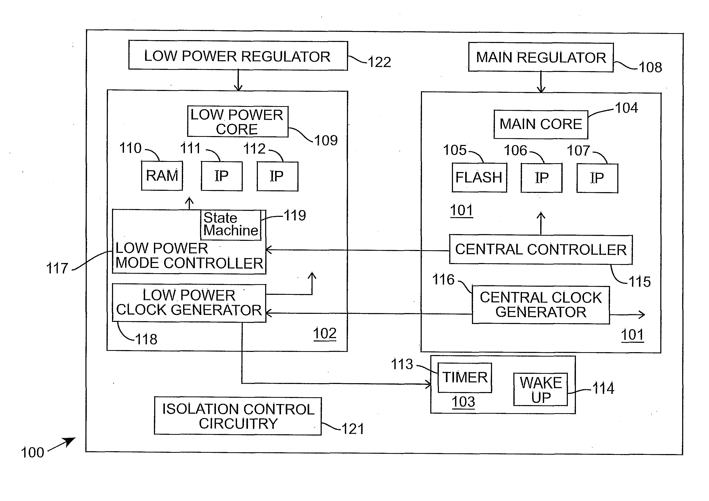
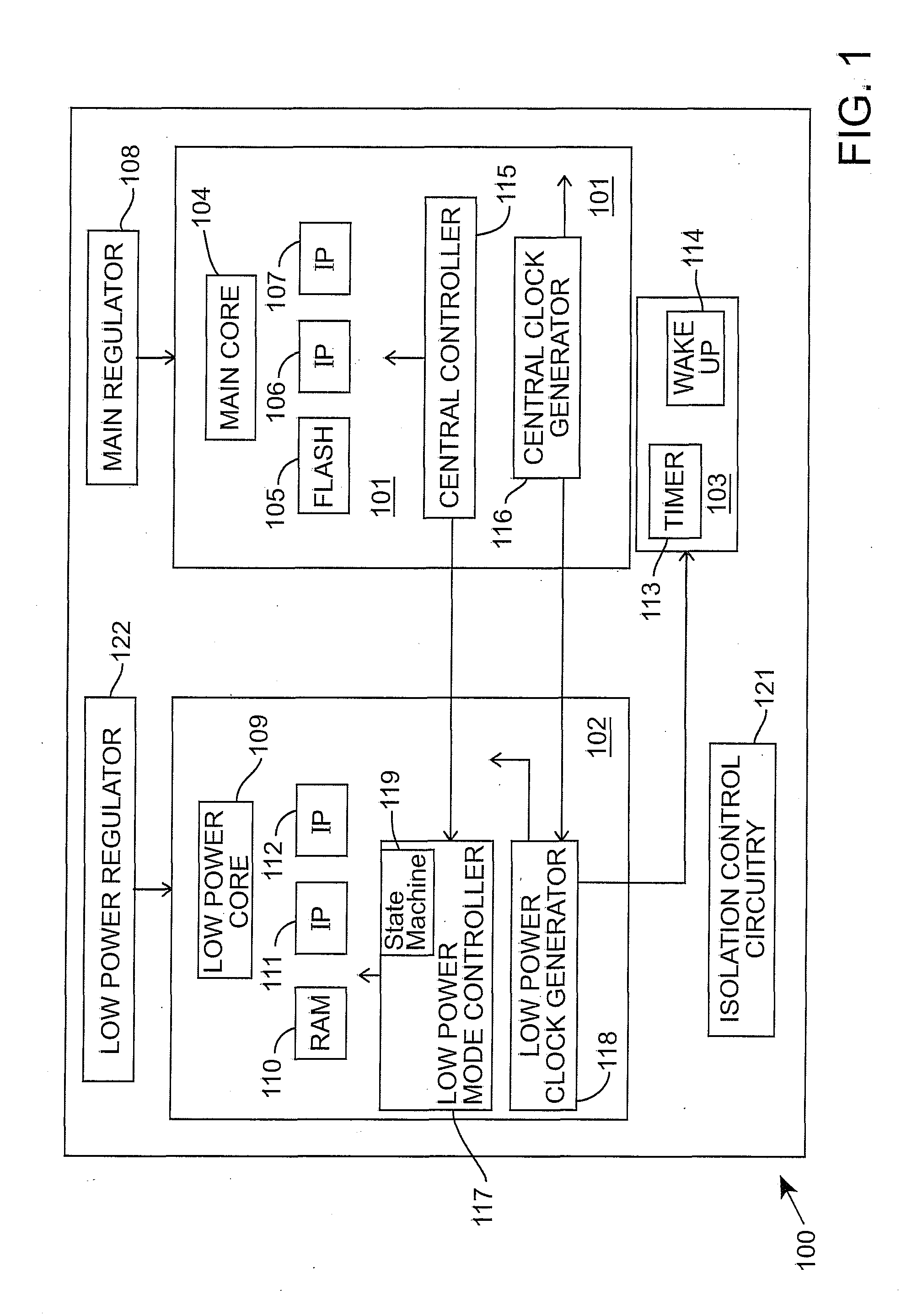
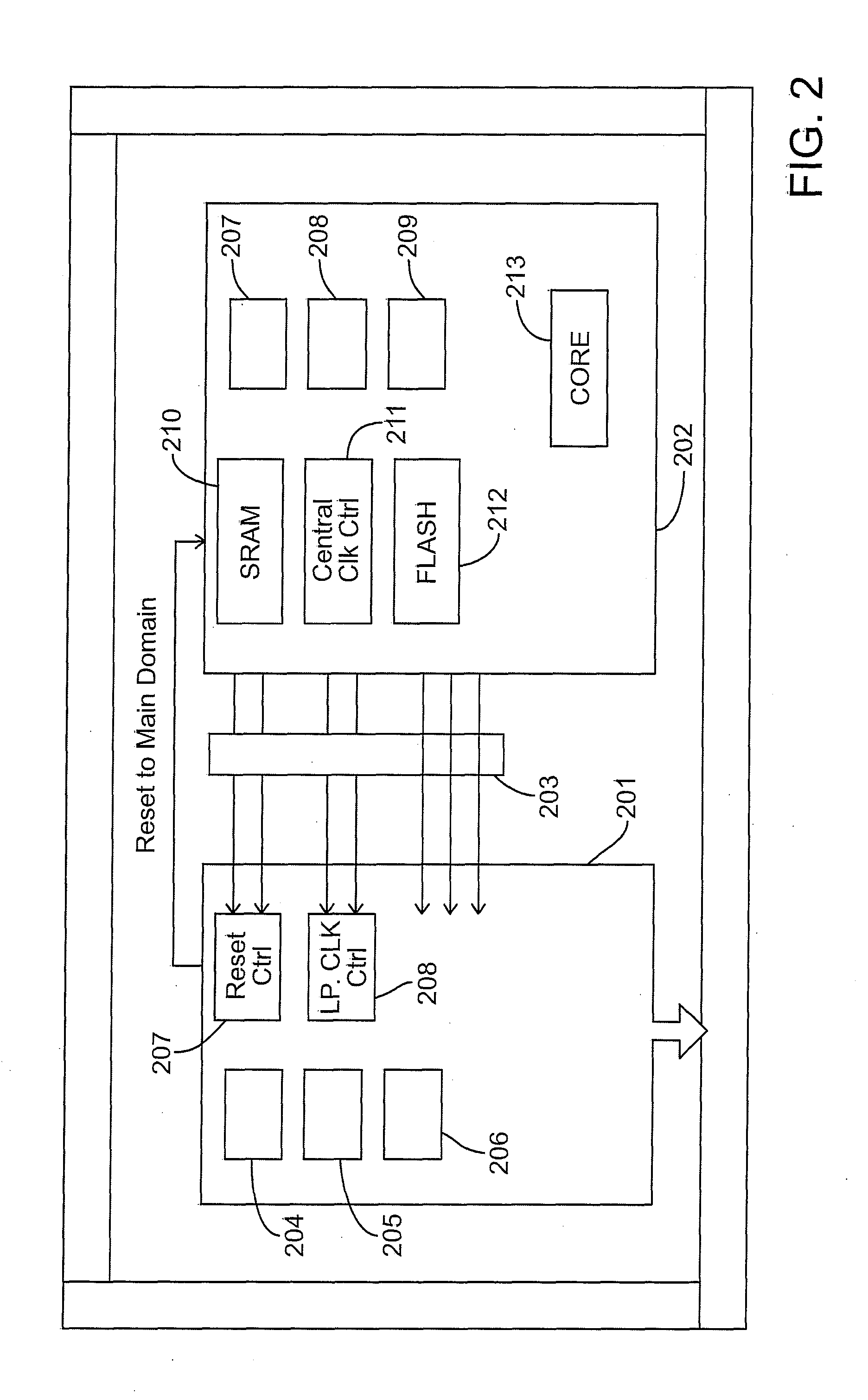
[0007]The detailed description set forth below in connection with the appended drawings is intended as a description of presently preferred embodiments of the invention, and is not intended to represent the only forms in which the present invention may be practised. It is to be understood that the same or equivalent functions may be accomplished by different embodiments that are intended to be encompassed within the spirit and scope of the invention. In the drawings, like numerals are used to indicate like elements throughout. Furthermore, terms “comprises,”“comprising,” or any other variation thereof, are intended to cover a non-exclusive inclusion, such that module, circuit, device components, structures and method steps that comprises a list of elements or steps does not include only those elements but may include other elements or steps not expressly listed or inherent to such module, circuit, device components or steps. An element or step proceeded by “comprises . . . a” does n...


PUM


Abstract

A power management system permits a small microcontroller subsystem or low power domain to continuously operate while a main subsystem domain is cycling from power on to off. The power management system supports asynchronous domains with common shared peripherals. The asynchronous domains operate as a single entity while in a full power mode with the peripheral and system resources being shared. The system can be used in automotive systems where most of the system is power-gated leaving just a power regulator controller, some counters and an input / output segment alive for wakeup purposes.

Description

BACKGROUND OF THE INVENTION[0001]The present invention relates generally to power management, and more particularly, to systems and methods for power management of different functional modes of operation of an integrated circuit such as a multi-core System on Chip (SOC).[0002]To manage power consumption, an SoC may be partitioned into various power domains such that each peripheral belongs to one of the power domains. An SoC will further have multiple modes where some of the peripherals will be active and some will be powered off. The mode where only a minimum required set of peripherals are active, is referred to as a Standby mode. The subset of the modules that are always alive are referred to as being in the alive domain and the subset of the modules that are power gated are referred to as being in the power gated domain. Typically, isolation cells are used to isolate the alive domain from the power gated domain. The different functional modes of operation typically reside in dif...

Claims


Application Information

Patent Timeline
Patent Type & Authority Patents(United States)
IPC IPC(8): G05F1/10G05F1/66H03K3/012
CPCH03K3/012G05F1/66G06F1/3287G06F1/3293Y02D10/00
Inventor SHARDA, GARIMACULSHAW, CARLDEVINE, ALANPATHAK, AKSHAY K.ROBERTSON, ALISTAIR P.
Owner NXP USA INC
Why Eureka
Try Eureka