AI technical title is built by PatSnap AI team. It summarizes the technical point description of the patent document.
a signal processor and in-line technology, applied in the direction of sound input/output, volume compression/expansion, instruments, etc., can solve the problems of inconvenient hardware, large expense, and increased signal overshoots or undershoots, so as to increase or decrease overshoots or undershoots.
Active Publication Date: 2015-11-24
BONGIOVI ACOUSTICS LLC
View PDF195 Cites 42 Cited by
Summary
Abstract
Description
Claims
Application Information
AI Technical Summary
This helps you quickly interpret patents by identifying the three key elements:
Problems solved by technology
Method used
Benefits of technology
Benefits of technology
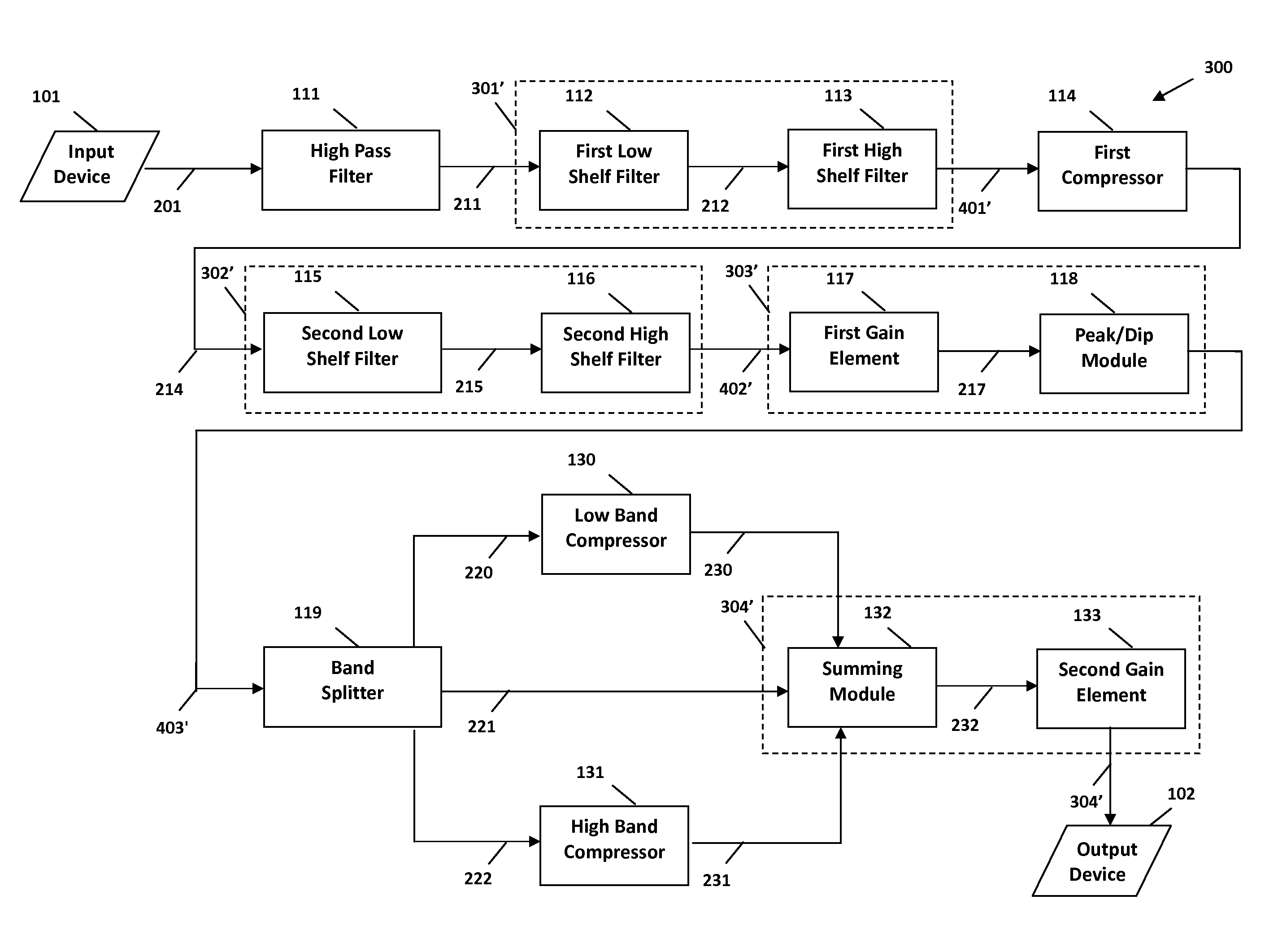
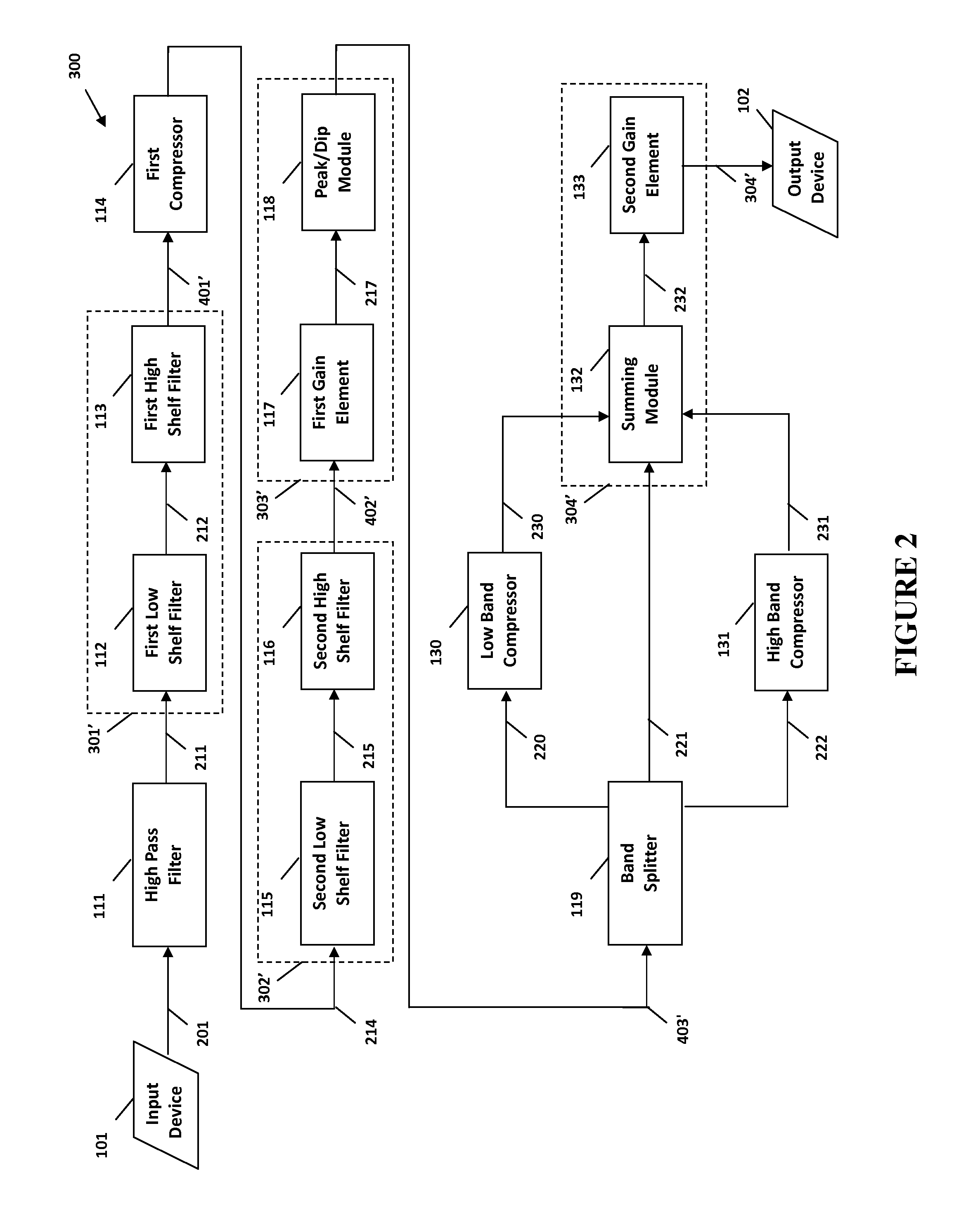
[0013]The second filtered signal from the second filter module is then processed with a first processing module to create a processed signal. In at least one embodiment, the first processing module may comprise a peak / dip module. In other embodiments, the first processing module may comprise both a peak / dip module and a first gain element. The first gain element may be configured to adjust the gain of the signal, such as the second filtered signal. The peak / dip module may be configured to shape the signal, such as to increase or decrease overshoots or undershoots in the signal.
Problems solved by technology
While various attempts have been made to reproduce studio-quality sound outside of the recording studio, those attempts have come at tremendous expense (usually resulting from advanced speaker design, costly hardware, and increased power amplification) and have achieved only mixed results.
Furthermore, the required hardware is inconvenient, and requires additional components and setup.
Method used
Image
Click on the blue label to locate the original text in one second.
Reading with bidirectional positioning of images and text.
Examples
Embodiment Construction
[0027]As illustrated by the accompanying drawings, the present invention is directed to systems, methods, and apparatuses for digitally processing an audio signal. Specifically, some embodiments relate to digitally processing an audio signal in order to deliver studio-quality sound in a variety of different consumer electronic devices.
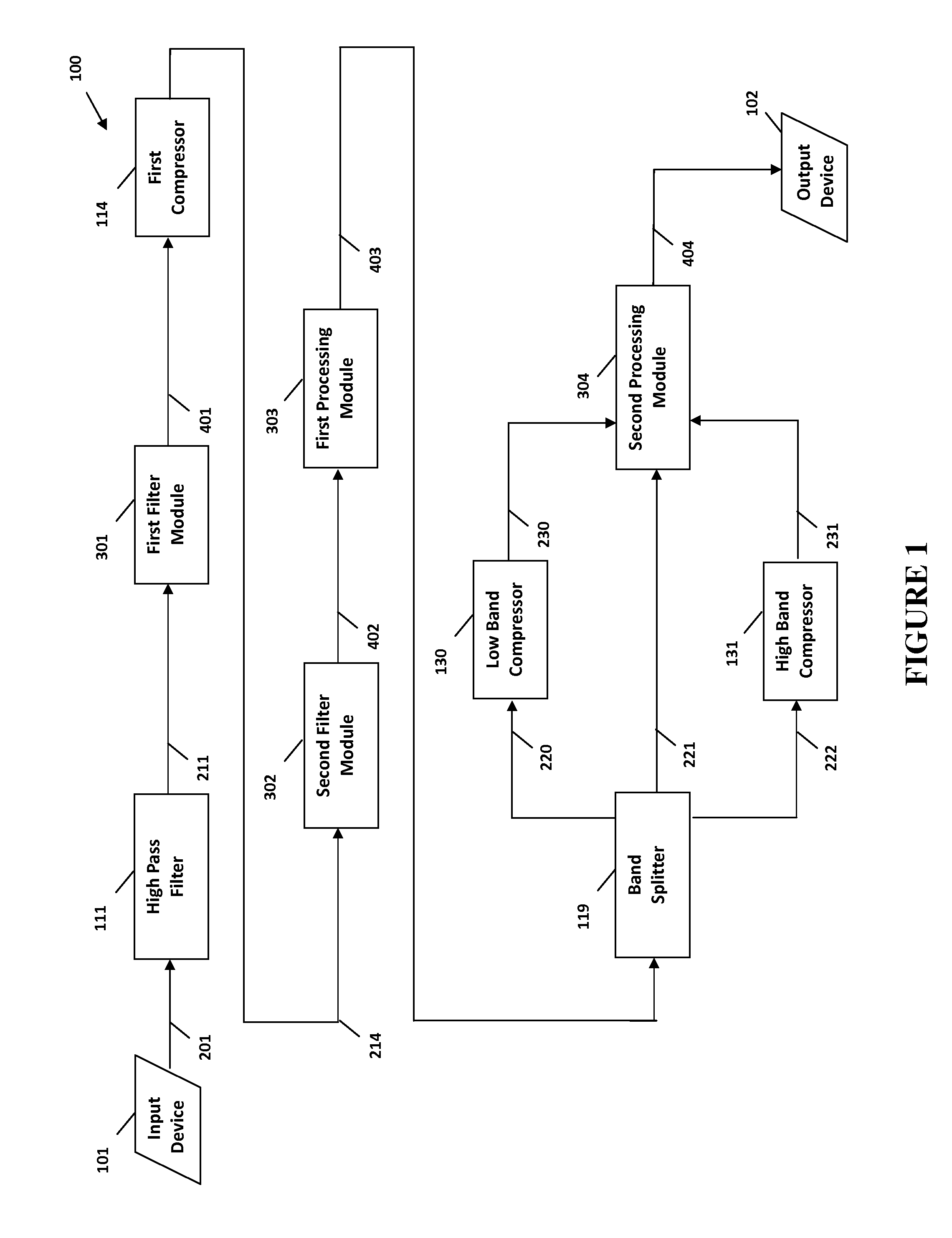
[0028]As schematically represented, FIG. 1 illustrates at least one preferred embodiment of a system 100 for digitally processing an audio signal, and FIG. 2 provides examples of several subcomponents and combinations of subcomponents of the modules of FIG. 1. Accordingly, and in these embodiments, the systems 100 and 300 generally comprise an input device 101, a high pass filter 111, a first filter module 301, a first compressor 114, a second filter module 302, a first processing module 303, a band splitter 119, a low band compressor 130, a high band compressor 131, a second processing module 304, and an output device 102.
[0029]The input device 101 is...
PUM
Abstract
The present invention provides for a communications cable for processing an input signal. Specifically, the present invention includes a communication cable having an input connector structured to receive an input signal, an audio enhancement module configured to process the input signal using a plurality of processing components in order to create an output signal, and an output connector structured to transmit the output signal.
Description
CROSS-REFERENCE TO RELATED APPLICATIONS[0001]This application claims priority to U.S. Provisional Application No. 61 / 908,402 filed on Nov. 25, 2013.[0002]This application is also a continuation-in-part of U.S. application Ser. No. 14 / 059,948 filed on Oct. 22, 2013 and which is a continuation-in-part of U.S. application Ser. No. 12 / 648,007 filed on Dec. 28, 2009 and which matured into U.S. Pat. No. 8,565,449 on Oct. 22, 2013, which is a continuation-in-part of U.S. application Ser. No. 11 / 947,301 filed on Nov. 29, 2007 and which matured into U.S. Pat. No. 8,160,274 on Apr. 17, 2012, which claims priority to U.S. Provisional Application No. 60 / 861,711 filed Nov. 30, 2006, and is a continuation-in-part of U.S. application Ser. No. 11 / 703,216, filed Feb. 7, 2007, which claims priority to U.S. Provisional Application No. 60 / 765,722, filed Feb. 7, 2006.[0003]Each of the above patents and applications is incorporated by reference herein in its entirety.FIELD OF THE INVENTION[0004]The prese...
Claims
Application Information
Patent Timeline
Application Date:The date an application was filed.
Publication Date:The date a patent or application was officially published.
First Publication Date:The earliest publication date of a patent with the same application number.
Issue Date:Publication date of the patent grant document.
PCT Entry Date:The Entry date of PCT National Phase.
Estimated Expiry Date:The statutory expiry date of a patent right according to the Patent Law, and it is the longest term of protection that the patent right can achieve without the termination of the patent right due to other reasons(Term extension factor has been taken into account ).
Invalid Date:Actual expiry date is based on effective date or publication date of legal transaction data of invalid patent.

