Mobile device

a mobile device and frame technology, applied in the direction of coupling device connection, antenna details, antennas, etc., can solve the problems of affecting the reception of mobile devices, changing the original frame structure, and affecting the beauty of the mobile device, so as to enhance the appearance design of the mobile devi

Active Publication Date: 2015-12-01
HTC CORP
View PDF18 Cites 9 Cited by
  • Summary
  • Abstract
  • Description
  • Claims
  • Application Information

AI Technical Summary

Benefits of technology

[0007]The subject application provides a mobile device, which uses a resonance element formed on a portion of a periphery of the mobile device to receive and transmit a radio frequency signal, and the resonance element with antenna function enhances the appearance design of the mobile device.
[0015]Based on the above, the metal frame of the subject application is formed on a portion of the periphery, and the resonance element is formed on a portion of the metal frame. Accordingly, the resonance element formed on a portion of the metal frame is used to form the loop antenna that operates in multiple frequency bands. In addition that the metal frame is used to form the antenna for the mobile device, the metal frame with the antenna function has a smooth streamline shape, which enhances the appearance design of the mobile device. Additionally, in comparison with the conventional technology, the clearance area that the mobile device requires is relatively reduced, which is conducive to the miniaturization of the mobile device.

Problems solved by technology

However, the appearance design of metallic texture usually requires combining a conductive structure into the mobile device, which may affect signal reception of the mobile device.
However, the formation of the notch changes the original structure of the frame and impairs the beautiful streamline appearance of the mobile device.
However, in the aforementioned disclosures, the formation of the gap damages the original structure of the frame, and the mobile device needs to have a sufficient clearance area at the bottom for forming the loop antenna or the inverted F antenna.

Method used


Image

  • Mobile device
  • Mobile device
  • Mobile device

Examples


Embodiment Construction

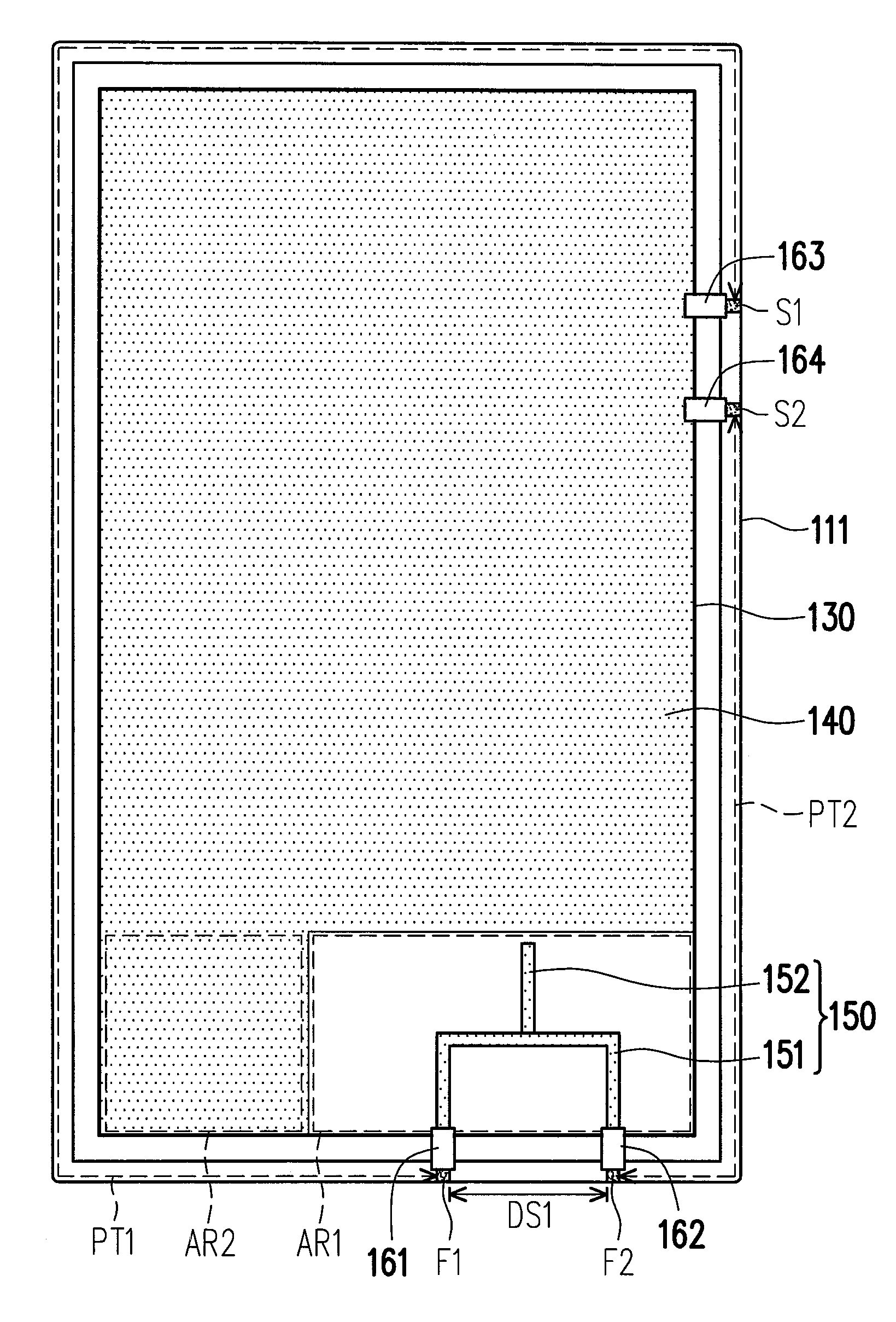
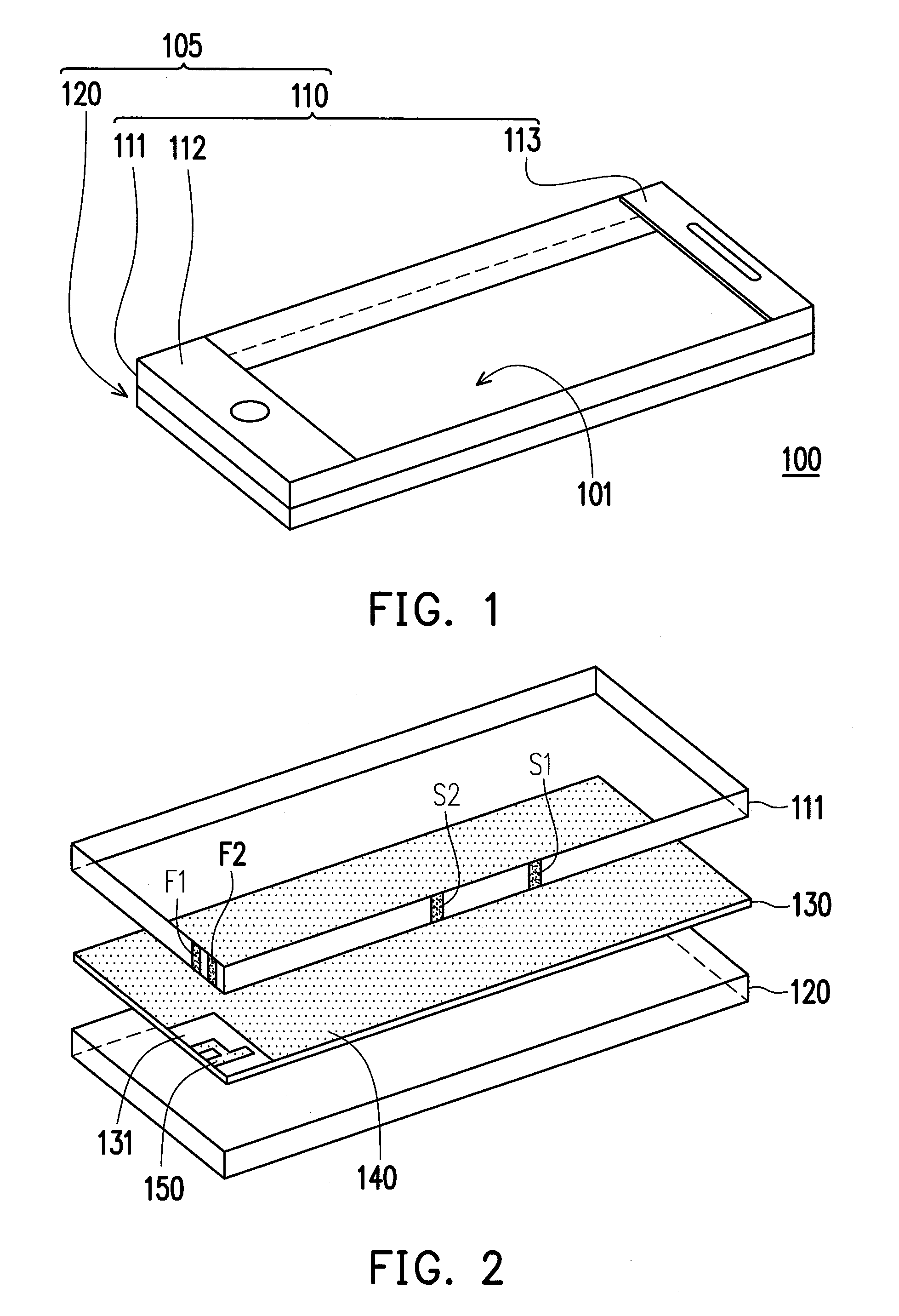
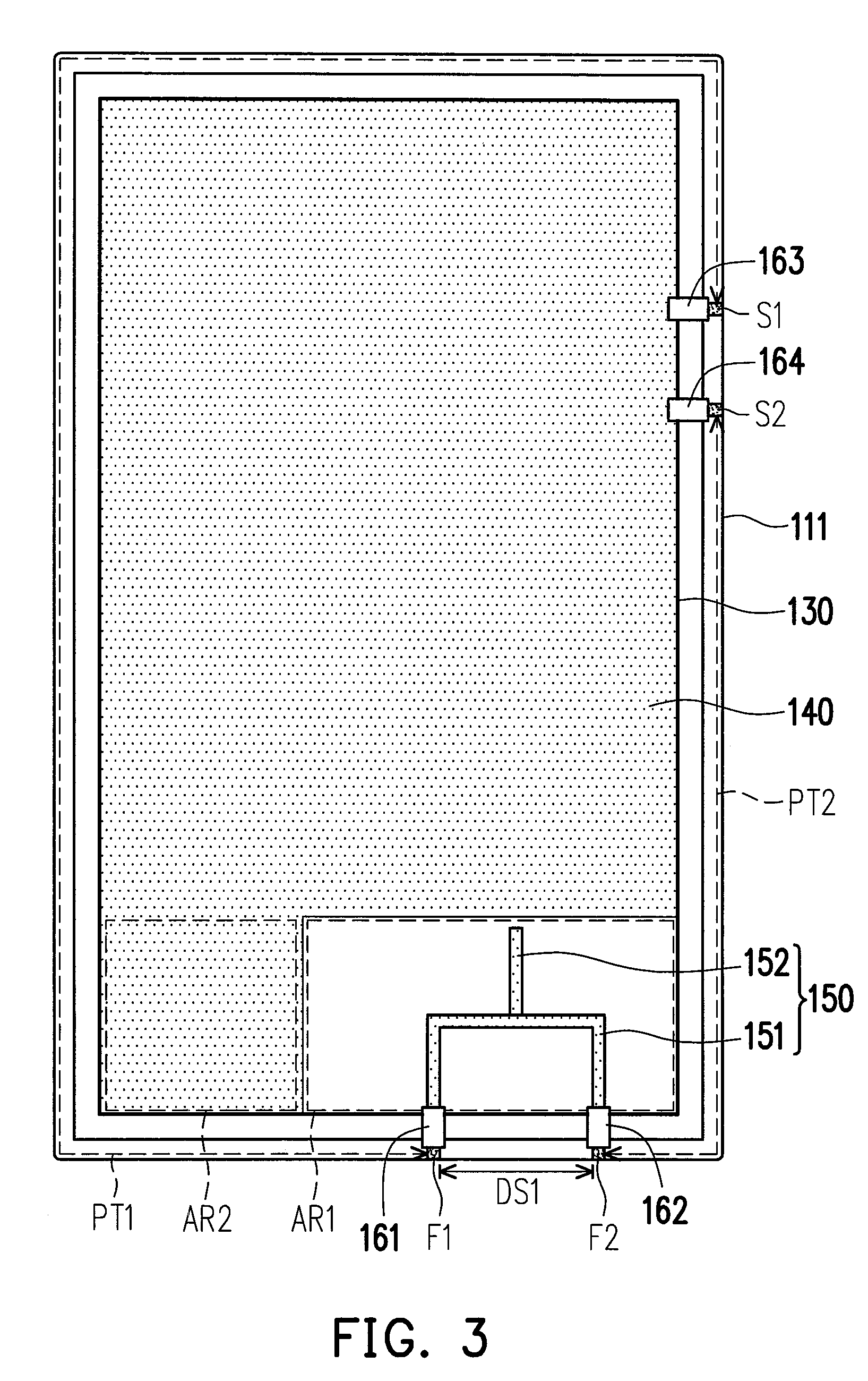
[0023]FIG. 1 is a schematic view of a mobile device according to an exemplary embodiment of the invention. Referring to FIG. 1, a mobile device 100 at least includes a periphery, a processor, an input module, a power supply module, a wireless transceiver module, etc., wherein the periphery 105 includes a upper housing 110 and a lower housing 120. The upper housing 110 includes a metal frame 111 and a plurality of frame extension sections 112-113. The upper housing 110 and the lower housing 120 may be integrated into one single housing. The metal frame 111 is formed on at least a portion of the periphery 105. It is noted that the metal frame 111 may be used to constitute an overall side wall of the periphery 105 (upper housing 110) and have an opening 101. The frame extension sections 112-113 are coupled to the metal frame 111 and partially cover the opening 101 of the metal frame 111. The uncovered part of the opening 101 is used for disposing (1) an integrated touch-display module ...


PUM


Abstract

A mobile device having a periphery and including a substrate, a feeding line, and a resonance element is provided. The substrate has a ground plane and the feeding line is disposed on the substrate. The resonance element is formed on at least a portion of the periphery. The resonance element is electrically connected to the feeding line and the ground plane respectively via a first feeding point and a first ground point, so as to form a first excitation path. The resonance element receives and transmits a first radio frequency signal and a second radio frequency signal via the first excitation path.

Description

BACKGROUND OF THE INVENTION[0001]1. Field of the Invention[0002]The subject application relates to a mobile device and particularly relates to a mobile device using a metal frame partially formed on a periphery thereof to form a loop antenna.[0003]2. Description of Related Art[0004]As mobile devices rapidly develop, the manufacturers not only need to improve the functions of their products but also need to make their products unique, so as to satisfy the demands from the market. For example, now mobile devices are mostly designed with appearances of metallic texture for emphasizing the uniqueness. However, the appearance design of metallic texture usually requires combining a conductive structure into the mobile device, which may affect signal reception of the mobile device.[0005]In view of this problem, some improvements have been proposed, e.g. U.S. Pat. No. 8,009,110, US 2011 / 0133995, and US 2011 / 0241949. Specifically, U.S. Pat. No. 8,009,110 discloses forming a notch on a frame ...

Claims


Application Information

Patent Timeline
Patent Type & Authority Patents(United States)
IPC IPC(8): H04B1/38H01Q1/24H01R13/6595H04B1/3888H01Q5/35H01Q5/10
CPCH04B1/38H01Q1/243H04B1/3888H01Q5/35H01R13/6595
Inventor TENG, PEI-LINGCHEN, YI-CHUN
Owner HTC CORP
Why Eureka
Try Eureka