Bone plate system and related methods

a technology of bone plate and bone plate, applied in the field of laminoplasty, can solve the problems of surgeons likely drilling, traditional procedures can be largely risky to perform, etc., and achieve the effects of adequate vertical and/or horizontal displacement, adequate visualization of the operative site, and increased visibility of the surgical si

Active Publication Date: 2015-12-15
NUVASIVE
View PDF11 Cites 2 Cited by
  • Summary
  • Abstract
  • Description
  • Claims
  • Application Information

AI Technical Summary

Benefits of technology

[0008]The present invention describes a bone plate system for use in an open door laminoplasty procedure. The laminoplasty fixation system of the present invention increases the safety and reproducibility of the procedure by eradicating the steps of drilling and screwing over an open spinal cord and an unstable hinged lamina. The open U-shaped plate design of the present invention facilitates the placement of the laminar screw before cuts are made to the laminae, eliminating the risks of drilling and / or screwing over an open cord and hinged lamina.
[0017]A template tool can be used to help mark a lamina, as an alternative to or in addition to using a bone plate, for placement of a laminar screw. The template tool includes a handle, rod and distal end. The handle provides grip and control of the template tool. The rod can be straight, curved, and / or bent in one or more locations, so as to provide sufficient vertical and / or horizontal displacement of the handle and rod portion from the surgical site during use to enable adequate visualization of the operative site during use. The distal end of the template tool includes an attachment which is shaped similarly to a first end of a bone plate to be used during the laminoplasty procedure. The attachment can be permanently fixed to the rod, or alternatively, removably attached so as to make the attachment interchangeable with various attachments. The attachment allows proper marking of a laminar screw site prior to use of the bone plate being used for fixation. The template tool provides increased visibility of the surgical site, allowing a surgeon to mark the laminar screw site while visibility is optimized, rather than when visibility may be obstructed, as during placement of the bone plate against the surgical site by hand.
[0018]The base of the attachment includes side segments extending laterally from base of the attachment. The side segments act as a guide, providing proper positioning of the U-shaped end of the attachment, by lining up where the lateral mass meets the lamina. The side segments are lined up before the surgeon marks the area for placing a laminar screw. The attachment can extend straight and perpendicularly from the distal end where the rod and attachment meet, or curved or bent, to accommodate the contours of the surgical site, while still allowing optimized visibility of the surgical site depending on the configuration of the handle and rod assembly.
[0019]In use, the laminoplasty fixation system described herein allows for an increase in safety and reproducibility over the traditional laminoplasty surgical technique. According to the novel technique described herein, after a standard C2 to T1 midline posterior exposure and visualization of the lateral masses, a first fixation element (e.g. “laminar screw”) can be placed in each lamina to which a bone plate is being applied. The first fixation elements should be placed at the midpoint of the lamina between the lateral mass and the curvature where the spinous process begins. This location can be determined by using a template tool described herein. The open side trough can then be cut completely through the lamina on the same side of the spinous process as the first fixation element. The hinge cut is then formed on the opposite side of the spinous process. The stability of the hinge should be tested to ensure that sufficient opening can be achieved and to evaluate the size of plate necessary for decompression. A bone plate of the appropriate size is then selected (and the corresponding graft, if being used, can be attached to the plate) and the plate can then be inserted by sliding the U-shaped slot of the plate under the head of the previously placed first fixation element. The plate is thus positioned such that the pair of first flanges is adjacent a first surface of the divided lamina. The first portion of the third flange is positioned adjacent to and potentially abuts the cut end of the divided lamina, and the second portion of the third flange is positioned adjacent to and potentially abuts at least a portion of a second surface of the divided lamina. Thus, the first crotch is generally in contact with the cut end of the lamina. The plate may then be used to lift the lamina until the second terminal end of the body portion of the plate contacts the cut edge of the lateral mass. Alternatively, the lamina can be lifted and held in an open position with a secondary instrument, for example a curette or a nerve hook, while the plate is engaged with the first fixation element. The plate is positioned such that the second crotch rests against the cut edge of the lateral mass, and the second flange is positioned adjacent the lateral mass. Once the bone plate is properly positioned against the lateral mass, the second fixation element(s) can be inserted through aperture(s) and into the lateral mass bone. At this point the lamina is securely propped open. The surgical incision can be closed, completing the procedure. Any number of bone plates can be inserted on any number of lamina without departing from the scope of the present invention.

Problems solved by technology

For this “open door” laminoplasty procedure, one challenge is to securely maintain the grooved portion of lamina or “lamina hinge portion” for proper healing.
This traditional procedure can be risky to perform largely because the cuts in the lamina are made before the hole for the laminar screw are drilled.
This means that the surgeon is likely drilling through an unstable lamina directly over otherwise exposed spinal cord.

Method used


Image

  • Bone plate system and related methods
  • Bone plate system and related methods
  • Bone plate system and related methods

Examples


first embodiment

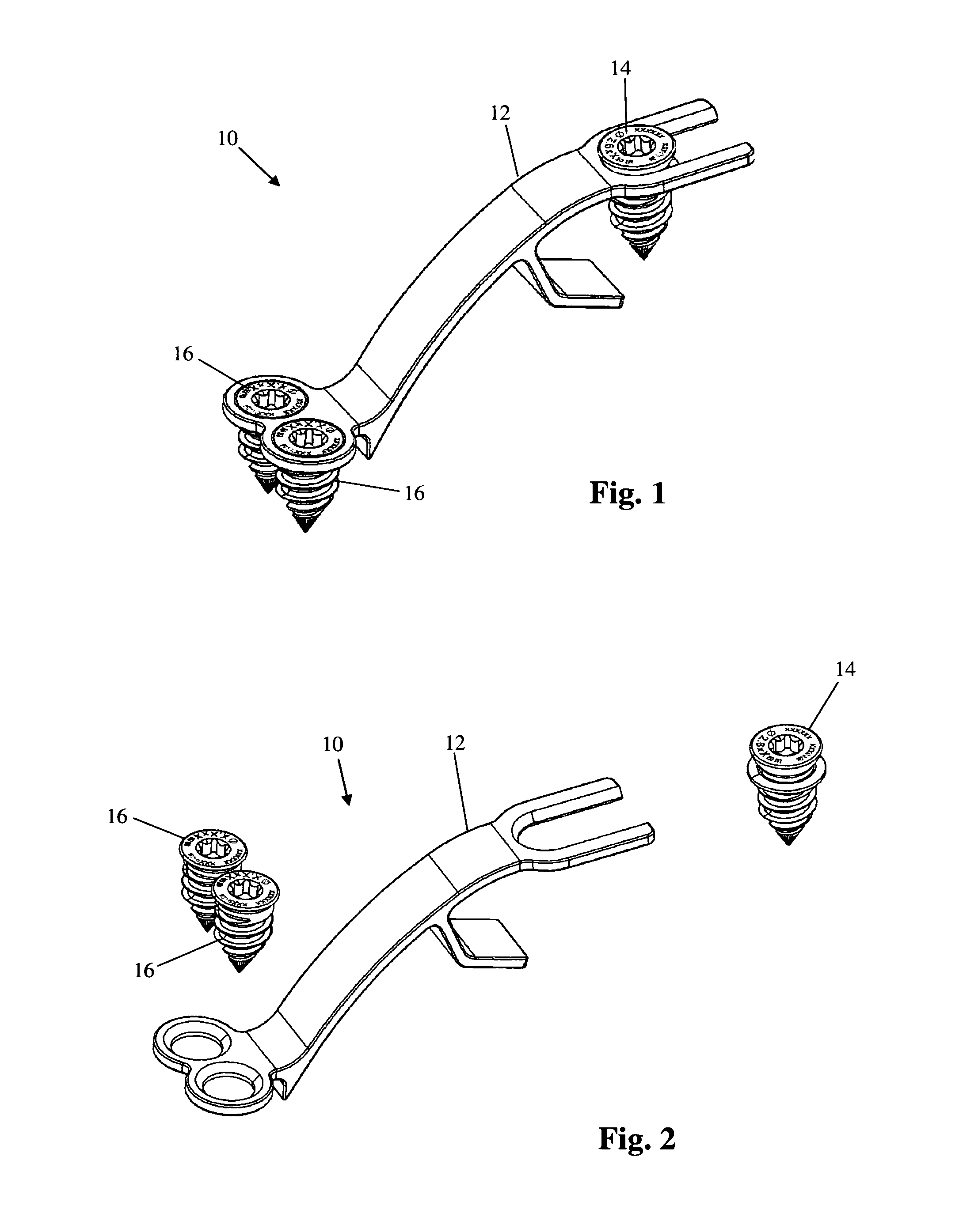
[0051]FIGS. 1-2 illustrate an example of a bone plate system 10 configured for use in a laminoplasty procedure, according to the present invention. By way of example only, the bone plate system 10 includes a bone plate 12, a first fixation element 14, and at least one second fixation element 16. The bone plate 12 is elongated and has a generally curved shape such that the plate 12 has an associated radius of curvature. The plate is sized and dimensioned to span a gap between a pair of bony segments, for example a pair of bony segments constituting a divided lamina. The first and second fixation elements 14, 16 are each configured to securely attach the bone plate 12 to the bony segments. Although shown by way of example in FIGS. 1 and 2 as being bone screws, other fixation elements are possible without departing from the scope of the present invention, for example tacks, nails, hooks, pins, sutures, adhesives, and the like.

[0052]The bone plate 12, first fixation element 14, and seco...

second embodiment

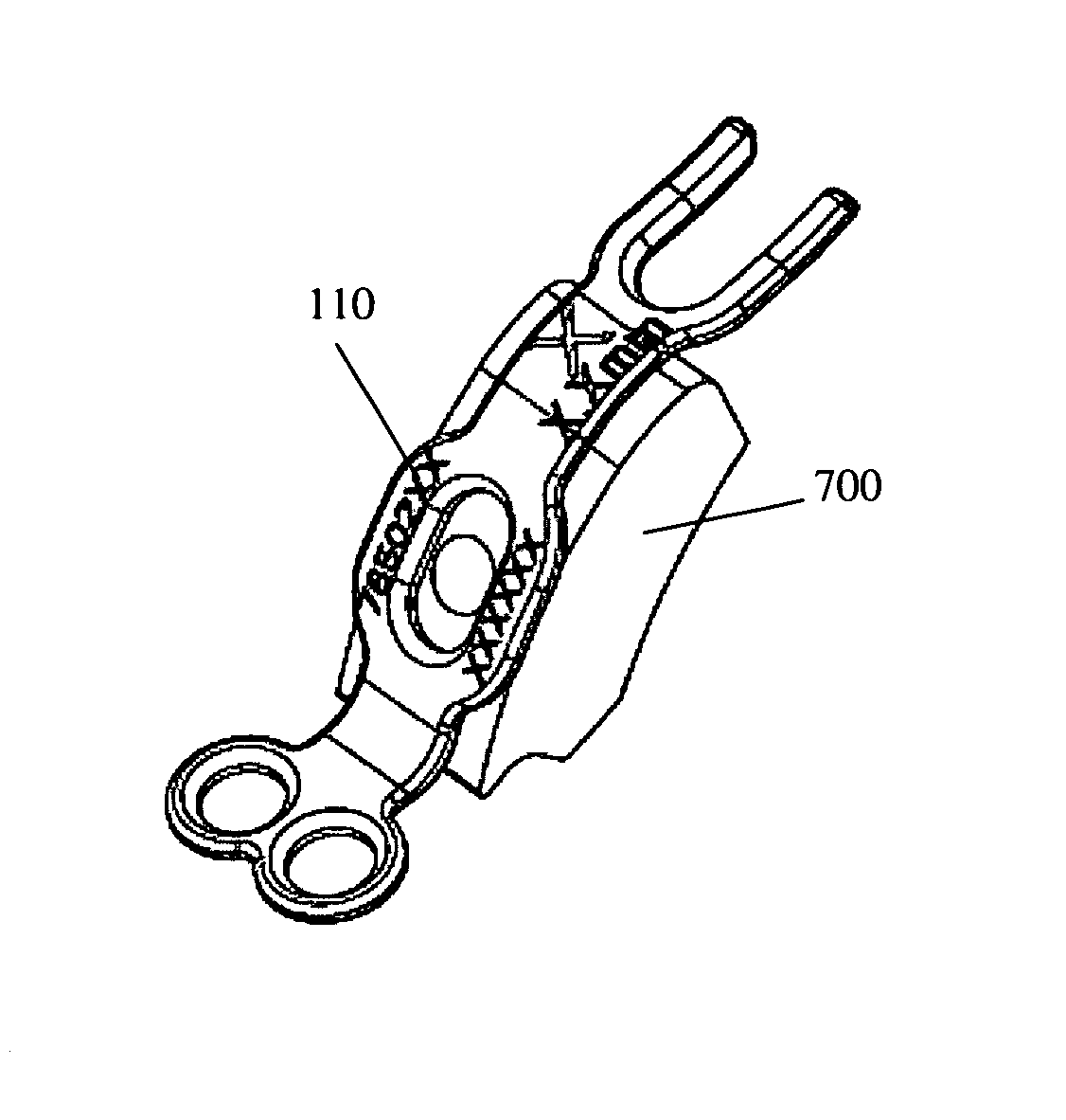
[0064]Referring to FIG. 17, an example of a bone plate system 110 is provided according to the present invention. The bone plate system 110 is similar to the bone plate system 10 described above except that the bone plate system 110 is configured to be used with a bone graft, for example the bone graft 700 shown in FIG. 32. By way of example only, the bone plate system 110 includes a bone plate 112, a first fixation element 114, at least one second fixation element 116, and a third fixation element 117. The bone plate 112 is elongated and has a generally curved shape such that the plate 112 has an associated radius of curvature. The plate 112 is sized and dimensioned to span a gap between a pair of bony segments, for example a pair of bony segments constituting a divided lamina. The first and second fixation elements 114, 116 are each configured to securely attach the bone plate 112 to the bony segments. The third fixation element 117 is configured to securely attach a bone graft, f...

third embodiment

[0068]FIG. 21 illustrates a bone plate system 210 according to the present invention. The bone plate system 210 is identical to the bone plate system 10 except that it is provided with a smaller size. Many different sizes of the bone plate system 10 / 210 may be provided without departing from the scope of the present invention.


PUM


Abstract

A bone plate system for use in an “open door” laminoplasty procedure, including a bone plate, a first fixation element, and at least one second fixation element. The bone plate is elongated and has a generally curved shape such that the plate has an associated radius of curvature. The plate is sized and dimensioned to span a gap between a pair of bony segments, for example a pair of bony segments constituting a divided lamina. The first and second fixation elements are each configured to securely attach the bone plate to the bony segments. The bone plate has a first end including a generally U-shaped slot extending therein such that the open end of the slot comprises a first terminal end of the plate.

Description

BACKGROUND OF THE INVENTION[0001]I. Field of the Invention[0002]The present invention relates to the field of laminoplasty, and, more particularly, to laminoplasty devices and methods.[0003]II. Discussion of the Prior Art[0004]Spinal stenosis is a degenerative narrowing of the spinal canal, nerve root canals and / or intervertebral foramina caused by bone and / or ligament hypertrophy in local, segmental or generalized regions. The narrowing results in compression of spinal nerves and nerve roots, causing a constellation of symptoms, including neck or lower back pain, neurogenic claudication and extremity pain. The leading cause of spinal stenosis is normal wear and tear on the spine, occurring in virtually the entire adult population during the natural process of aging, although spinal stenosis can occur at any age due to trauma, disease, or some medical conditions.[0005]Surgery is currently the only treatment designed and proven to provide long term relief from spinal stenosis. One wa...

Claims


Application Information

Patent Timeline
Patent Type & Authority Patents(United States)
IPC IPC(8): A61B17/88A61B17/80A61B17/70A61B17/86
CPCA61B17/7071A61B17/808A61B17/8625A61B17/68A61B17/80A61F2/2846
Inventor STEVENSON, TARACURRAN, MATTHEWSCHWARTZ, DAVIDBROWN, CHRISTOPHERORELLANA, JODYBROTMAN, MICHAEL
Owner NUVASIVE
Why Eureka
Try Eureka