
Stretch roll forming

a technology of stretching roll and rolling pin, which is applied in the direction of metal-working feeding device, manufacturing tool, positioning device, etc., can solve the problems of limited maximum normal force that can be applied and limited magnitude of compressive stress sustainable, so as to reduce the spring back and residual stress in the fabricated component, and the effect of light and strong parts

Active Publication Date: 2015-12-29
FAIRMOUNT TECH
View PDF25 Cites 2 Cited by
  • Summary
  • Abstract
  • Description
  • Claims
  • Application Information

AI Technical Summary

Benefits of technology

This approach enables the formation of complex shapes with reduced residual stresses and spring back, allowing for the creation of lighter and stronger components while minimizing the need for multiple shaping processes and dies, thus lowering production costs and time.

Problems solved by technology

The maximum normal force that can be applied is limited by the ability of the body to withstand the compressive stress without yielding.
The magnitude of the compressive stress sustainable may be limited by other stresses in the body.
Thus it is likely that there may always be a little more strain at the contact surfaces than subsurface and will lead to the burnishing effect identified earlier.

Method used


Image

  • Stretch roll forming
  • Stretch roll forming
  • Stretch roll forming

Examples


Embodiment Construction

[0031]Roll forming is a fabrication process of forming a work piece to a desired geometry by applying suitable forces by a plurality of roller stations that are precisely located and shaped with respect to a work piece. Forming is accomplished by relative motion between the work piece and a plurality of roller stations. The work piece can be sheet stock or a segment of stock of some preformed shape. In the stretch roll forming of the present invention, specific torque is applied to one or more of the rollers to cause a stretch that assists in forming the part into the desired shape while at the same time reducing residual stress in the work piece.

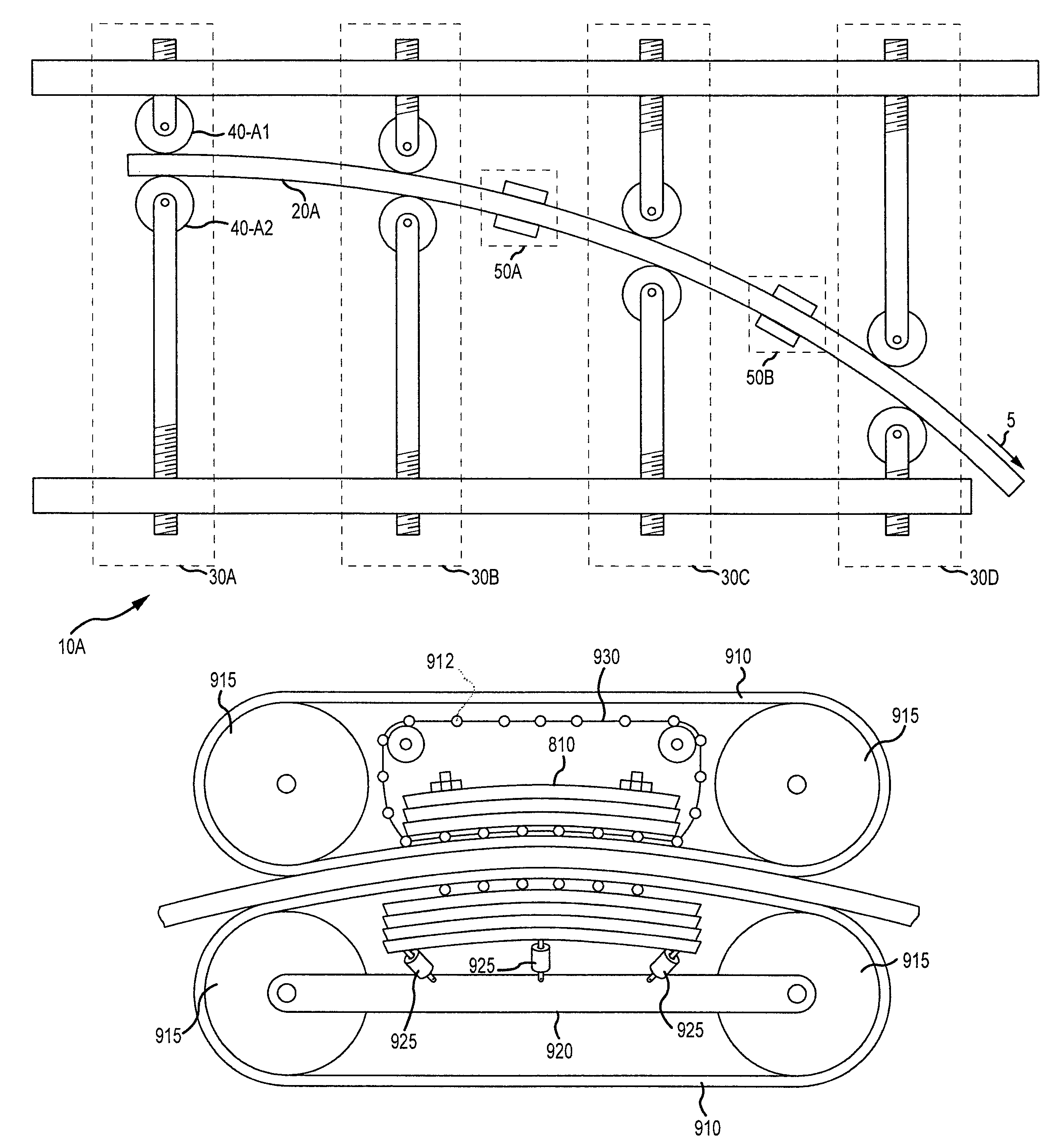
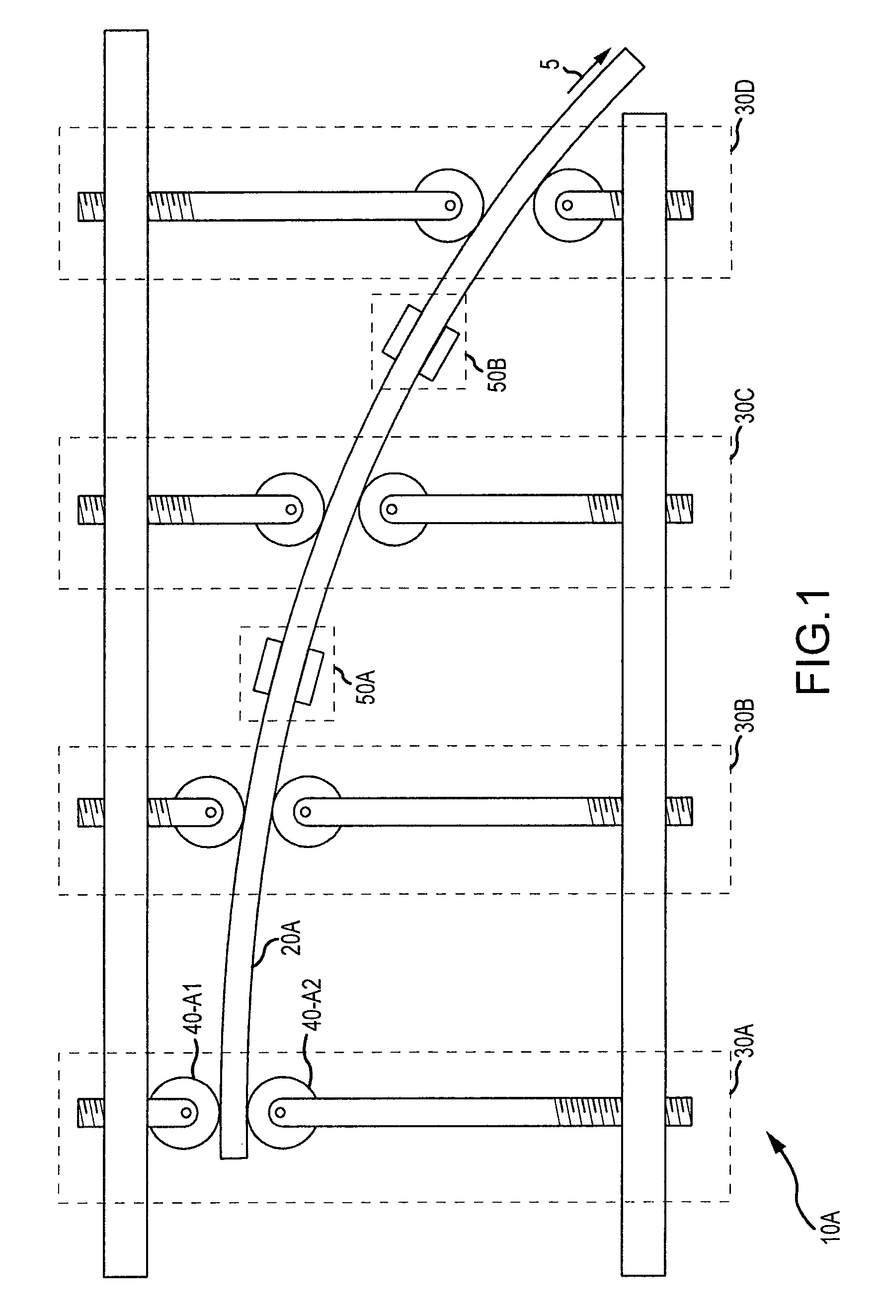
[0032]FIG. 1 illustrates the basic system 10A of the present invention. Each of a plurality of sequentially arranged roller stations 30A, 30B, 30C, and 30D includes a set of rollers, each set having at least two rollers where a roller is sometimes referred to as a die.

[0033]In the embodiment illustrated in FIG. 1, a flat strip is stretched ...


PUM

PropertyMeasurementUnit
aspect ratioaaaaaaaaaa
traction forcesaaaaaaaaaa
radiusaaaaaaaaaa

Abstract

A method of forming includes applying a stretching force along a linear axis of a work piece and forming the work piece while the stretching force is applied.

Description

[0001]This application claims the benefit of U.S. Provisional Application Ser. No. 61 / 171,247, filed Apr. 21, 2009 and entitled Stretch Roll Forming.FIELD OF THE INVENTION[0002]The present invention relates to a method and apparatus for forming metal.BACKGROUND OF THE INVENTION[0003]Complex curved metal components are formed to a desired shape by the mechanical action of dies (roll forming) or by application of other external forces, such as stretching, hydraulic fluid, induction coils, etc. In most roll forming processes, unique sets of dies need to be fabricated and used for each specific forming operation of each part. Moreover, many shapes require at least one additional shaping process in order to achieve the desired shape, such as stretch forming. This increases the cost and lead time of production. The U.S. patent to Gerald Hackstock, U.S. Pat. No. 6,286,352, entitled Stretch Roll Forming Apparatus Using Frusto-Conical Rolls is exemplary of the effort to combine the roll and ...

Claims


Application Information

Patent Timeline
Patent Type & Authority Patents(United States)
IPC IPC(8): B21D1/05B21D5/08B21D11/02B21D5/14B21D43/08B21D43/09B21D1/02B21D5/06
CPCB21D5/08B21D11/02B21D1/02B21D43/09B21D5/06B21D5/14B21D43/08B21D1/05
Inventor MADHAVAN, VISSAKET, MAHDI
Owner FAIRMOUNT TECH
Learn More