Stretch Roll Forming

a technology of stretching roll and rolling pin, which is applied in the direction of metal-working feeding device, manufacturing tool, positioning device, etc., can solve the problems of limited maximum normal force that can be applied and limited magnitude of compressive stress sustainable, so as to reduce the spring back and residual stress in the fabricated component, and the effect of light and strong parts

Active Publication Date: 2010-10-21
FAIRMOUNT TECH
View PDF25 Cites 23 Cited by
  • Summary
  • Abstract
  • Description
  • Claims
  • Application Information

AI Technical Summary

Benefits of technology

[0010]Grasping a specimen via rollers, so that the specimen moves with respect to the grips, causes the stretch as well as the burnishing strains to be uniformly spread throughout the specimen, permitting much more strain, hardening and compressive residual stress on the surface, thereby leading to an overall lighter and stronger part.
[0012]The present invention is based on the concept that sets of rollers can be mounted on suitable mechanisms and used as reconfigurable ‘dies’ that guide the formation of parts into desired shapes. The same rollers, when suitable driving torque is applied to them, are also used to stretch the part while it is being formed. The stretch-roll aspect of the forming operation also includes bending of the metal work piece while a tensile force is exerted on it. In operation, the work piece may be a sheet or a structural section such as a T-section or pipe. The work piece is formed using a plurality of roller sets that exert a tensile force on the work piece to form it into a desired shape. The tensile loading that is exerted while forming the part reduces spring back and residual stresses in the fabricated component. The stretch of the work piece is controlled by the rotational speed of the roller sets and the torque on the rollers. The position and orientation of the roller sets is dynamically configured in one or more planes to control and vary the contour along the length of the work piece. Sensors provide feedback to adaptively measure and control the stretch in each section of the work piece as well as its geometry.
[0013]The advantage of using many sets of relatively small rollers to stretch components, as opposed to using two big rolls on opposite sides to grip a part and pull it in opposite directions, as shown in the Hackstock patent, U.S. Pat. No. 6,286,352, is that each contact between a roller and the component can be small. Thus, normal and stretch forces can be transmitted into curved parts of a work piece without flattening them out. The small stretch forces exerted by each roller set add cumulatively, leading to stretch forces large enough to stretch parts plastically.

Problems solved by technology

The maximum normal force that can be applied is limited by the ability of the body to withstand the compressive stress without yielding.
The magnitude of the compressive stress sustainable may be limited by other stresses in the body.
Thus it is likely that there may always be a little more strain at the contact surfaces than subsurface and will lead to the burnishing effect identified earlier.

Method used


Image

  • Stretch Roll Forming
  • Stretch Roll Forming
  • Stretch Roll Forming

Examples


Embodiment Construction

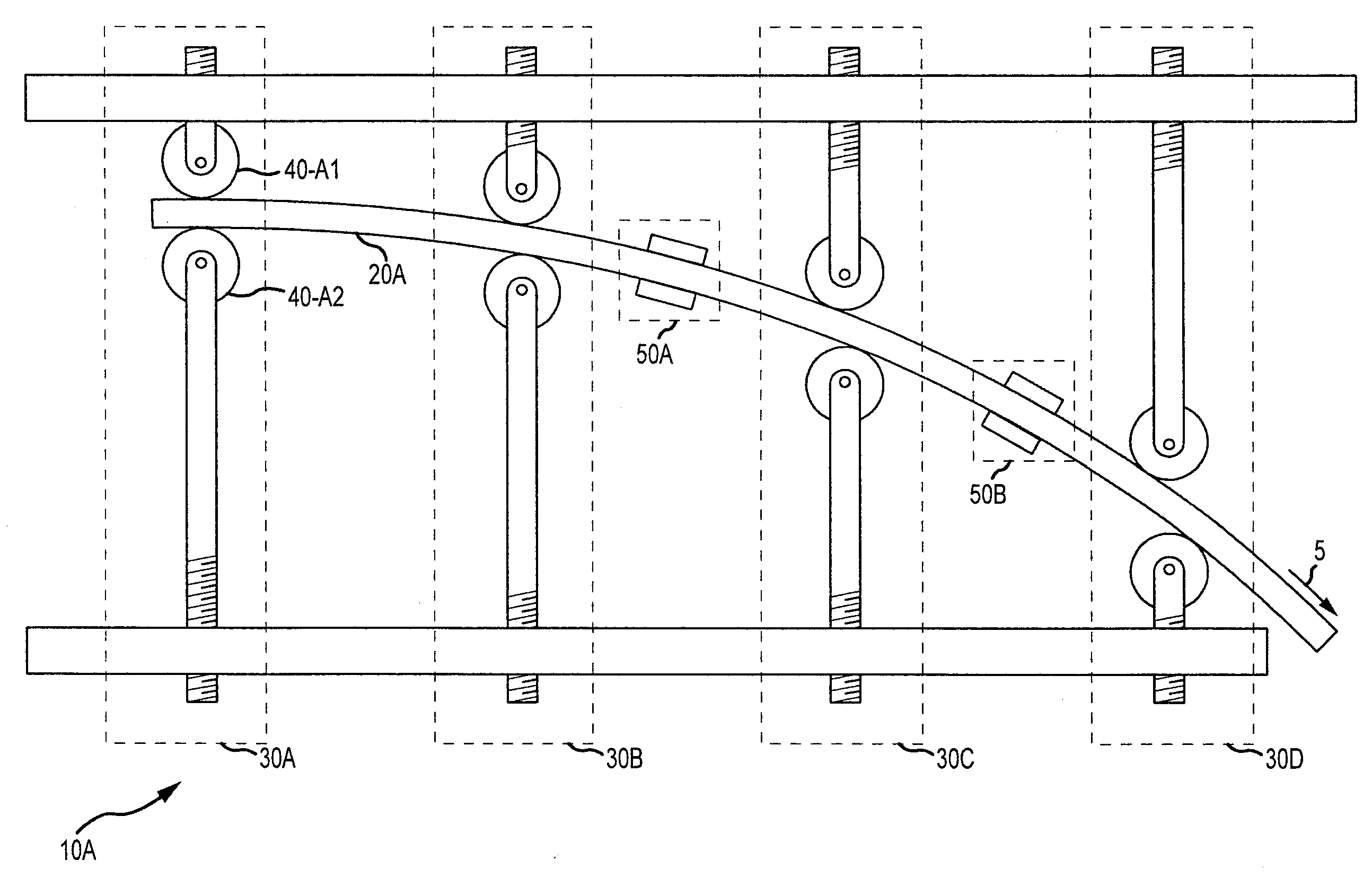
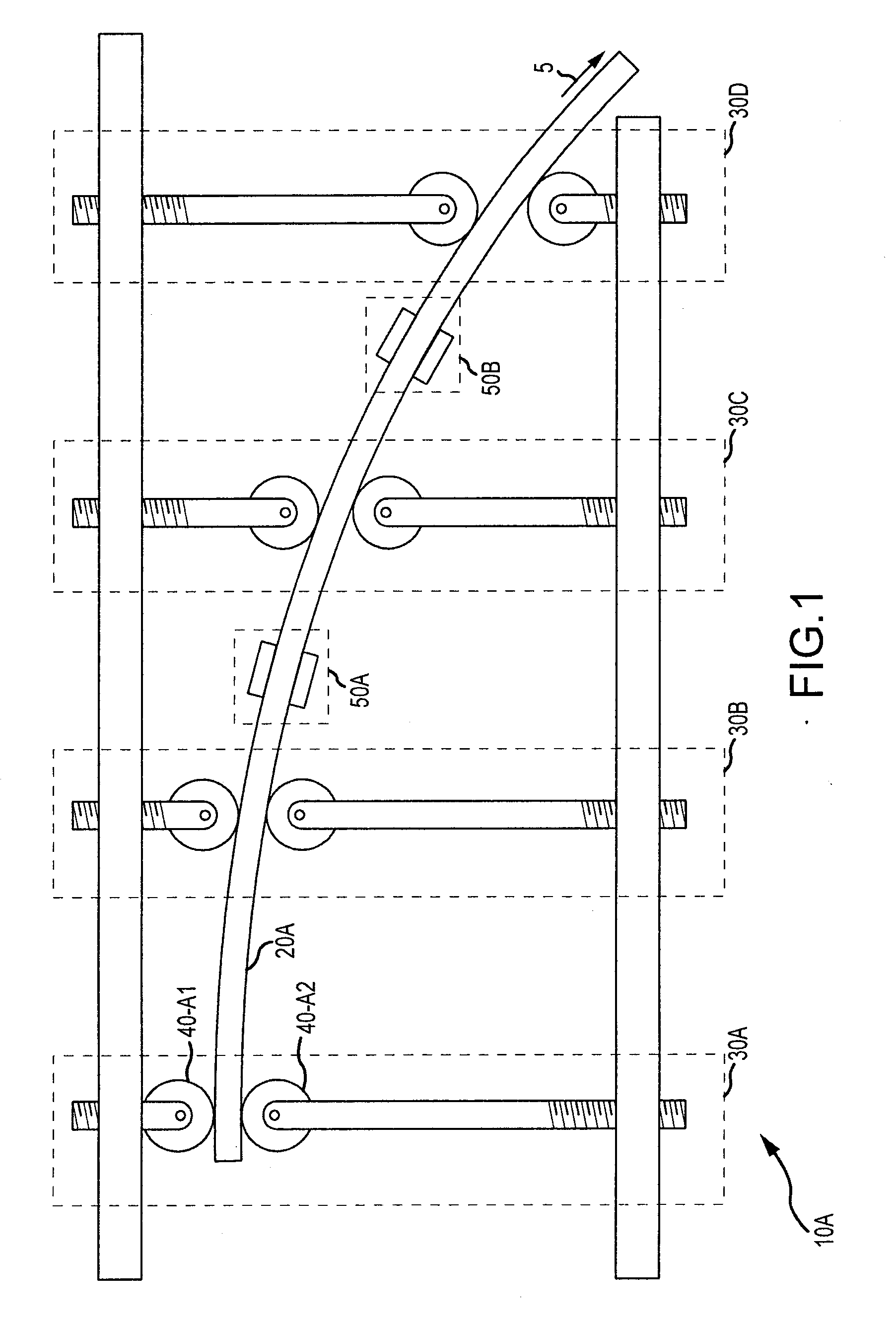
[0031]Roll forming is a fabrication process of forming a work piece to a desired geometry by applying suitable forces by a plurality of roller stations that are precisely located and shaped with respect to a work piece. Forming is accomplished by relative motion between the work piece and a plurality of roller stations. The work piece can be sheet stock or a segment of stock of some preformed shape. In the stretch roll forming of the present invention, specific torque is applied to one or more of the rollers to cause a stretch that assists in forming the part into the desired shape while at the same time reducing residual stress in the work piece.

[0032]FIG. 1 illustrates the basic system 10A of the present invention. Each of a plurality of sequentially arranged roller stations 30A, 30B, 30C, and 30D includes a set of rollers, each set having at least two rollers where a roller is sometimes referred to as a die.

[0033]In the embodiment illustrated in FIG. 1, a flat strip is stretched ...


PUM

PropertyMeasurementUnit
aspect ratioaaaaaaaaaa
stretching forceaaaaaaaaaa
torqueaaaaaaaaaa

Abstract

A method of forming includes applying a stretching force along a linear axis of a work piece and forming the work piece while the stretching force is applied.

Description

[0001]This application claims the benefit of U.S. Provisional Application Ser. No. 61 / 171,247, filed Apr. 21, 2009 and entitled Stretch Roll Forming.FIELD OF THE INVENTION[0002]The present invention relates to a method and apparatus for forming metal.BACKGROUND OF THE INVENTION[0003]Complex curved metal components are formed to a desired shape by the mechanical action of dies (roll forming) or by application of other external forces, such as stretching, hydraulic fluid, induction coils, etc. In most roll forming processes, unique sets of dies need to be fabricated and used for each specific forming operation of each part. Moreover, many shapes require at least one additional shaping process in order to achieve the desired shape, such as stretch forming. This increases the cost and lead time of production. The U.S. patent to Gerald Hackstock, U.S. Pat. No. 6,286,352, entitled Stretch Roll Forming Apparatus Using Frusto-Conical Rolls is exemplary of the effort to combine the roll and ...

Claims


Application Information

Patent Timeline
Patent Type & Authority Applications(United States)
IPC IPC(8): B21D5/14
CPCB21D5/08B21D11/02B21D5/06B21D1/02B21D43/08B21D1/05B21D43/09B21D5/14
Inventor MADHAVAN, VISSHAH, ANILSAKET, MAHDISWAMINATHAN, PALANIVELPLUENNEKE, HAROLD CURTIS
Owner FAIRMOUNT TECH
Why Eureka
Try Eureka