
Image pickup apparatus, image processing system, image pickup system, image processing method, and non-transitory computer-readable storage medium

a computer-readable storage medium and image processing technology, applied in the field of image processing system, image processing method, image processing method, etc., can solve the problems of inability to restore the frequency component in which an mtf (modulation transfer function) is small, the quality of the shot image is deteriorated, and the inability to correct the shot imag

Active Publication Date: 2015-12-29
CANON KK
View PDF22 Cites 0 Cited by
  • Summary
  • Abstract
  • Description
  • Claims
  • Application Information

AI Technical Summary

Benefits of technology

[0007]The present invention provides an image pickup apparatus, an image processing system, an image pickup system, an image processing method, and a non-transitory computer-readable storage medium which are capable of restoring a frequency component lost due to aberration or diffraction in a shot image.

Problems solved by technology

However, the quality of the shot image is deteriorated due to an influence of aberration or diffraction by an optical system.
However, in the image correcting method of using the inverse filter, a frequency component in which an MTF (Modulation Transfer Function) is small cannot be restored.
In addition, since it is necessary to have a special optical system configured by inserting the phase modulation element at the time of shooting an image, a shot image cannot be corrected.
On the other hand, since the purpose of the method disclosed in Japanese Patent No. 4872862 is to remove the blurring caused by the hand movement (the hand shake) or the defocusing, similarly it cannot restore a frequency component in which the MTF is small due to the influence of the aberration or the diffraction.

Method used


Image

  • Image pickup apparatus, image processing system, image pickup system, image processing method, and non-transitory computer-readable storage medium
  • Image pickup apparatus, image processing system, image pickup system, image processing method, and non-transitory computer-readable storage medium
  • Image pickup apparatus, image processing system, image pickup system, image processing method, and non-transitory computer-readable storage medium

Examples


embodiment 1

(Embodiment 1)

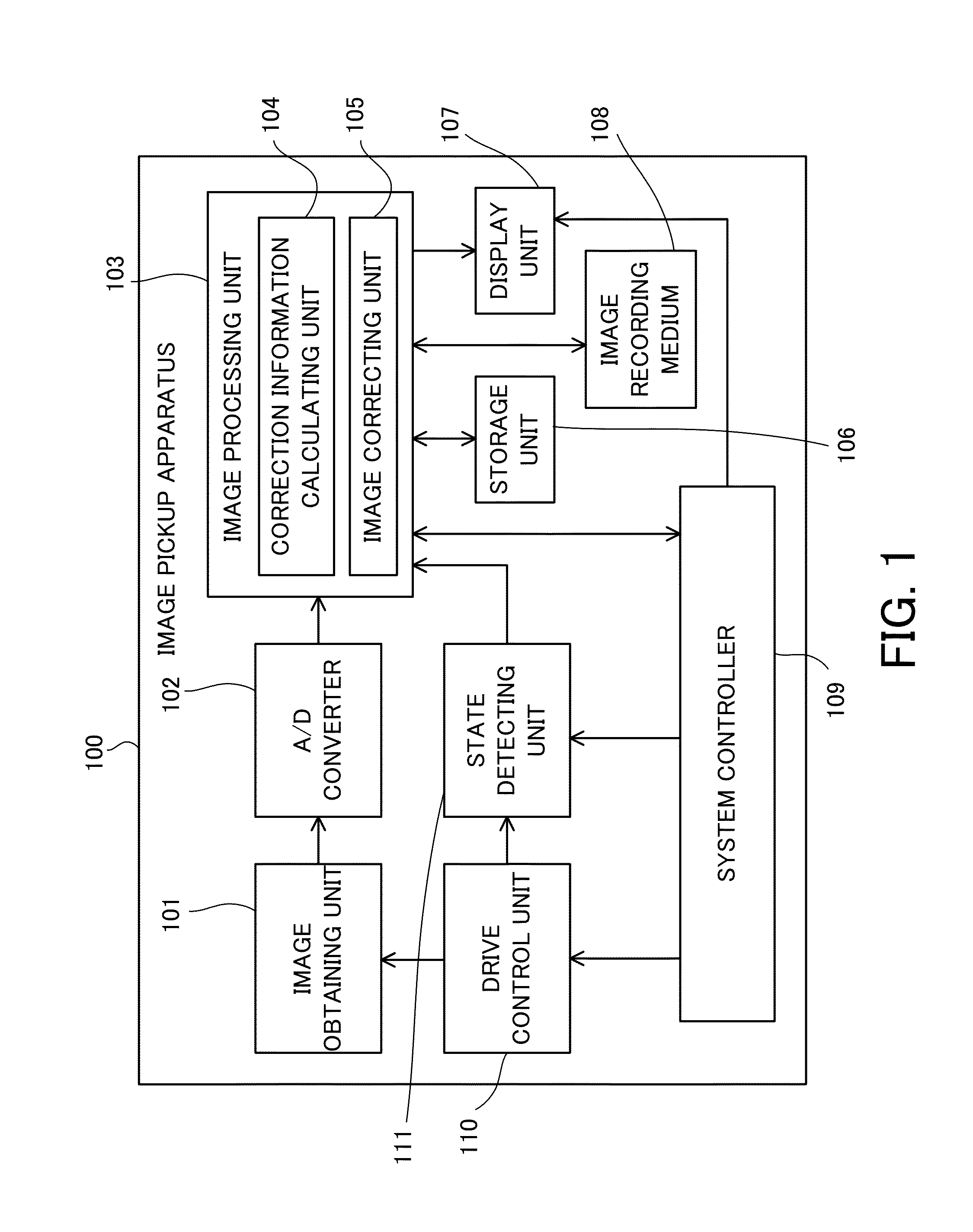
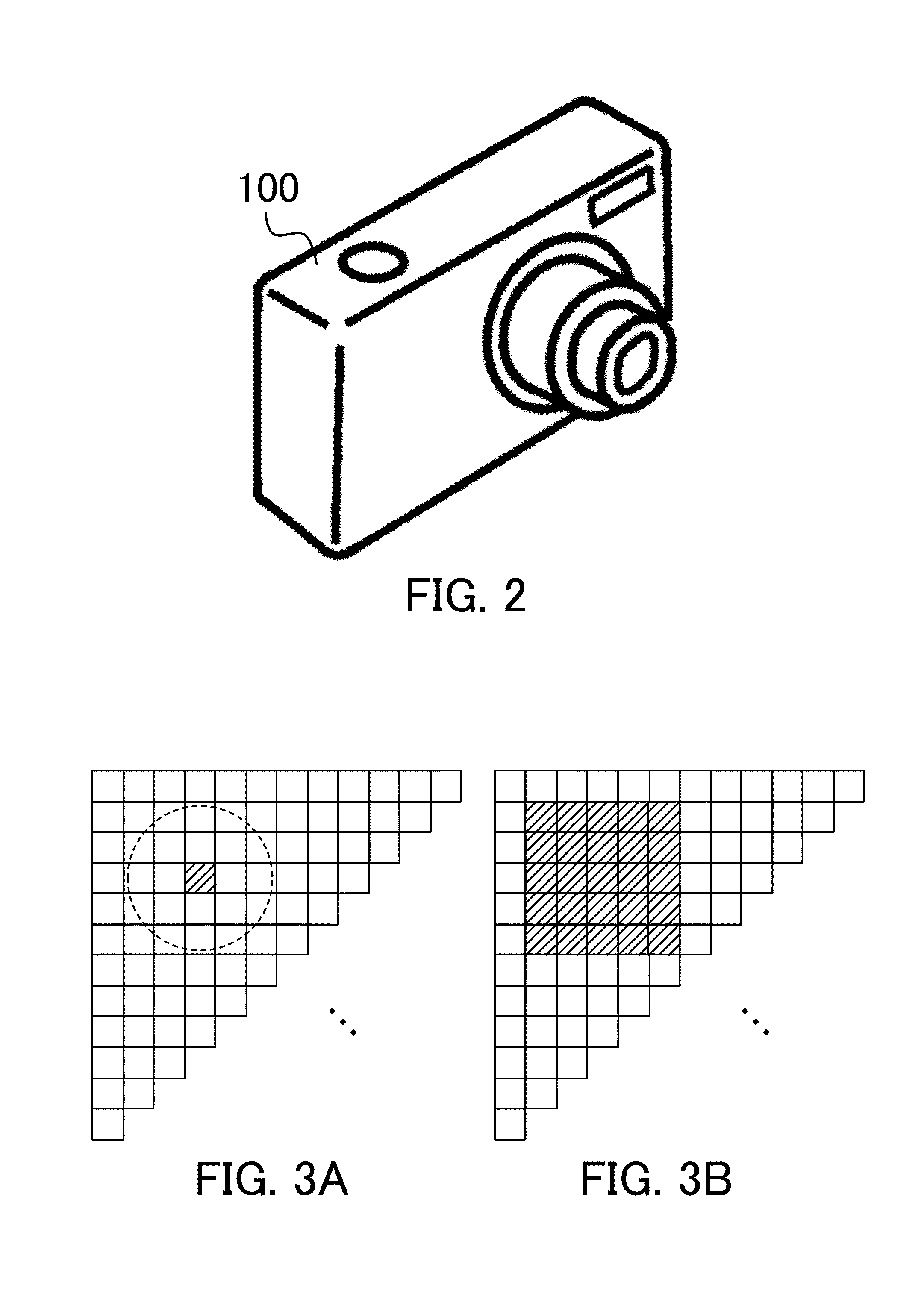
[0027]First of all, referring to FIGS. 1 and 2, an image pickup apparatus in Embodiment 1 of the present invention will be described. FIG. 1 is a block diagram of an image pickup apparatus 100 in the present embodiment. FIG. 2 is an external view of the image pickup apparatus 100. The image pickup apparatus 100 is configured to generate a second image (a restored image) based on a first image (a shot image) obtained via an image pickup optical system.

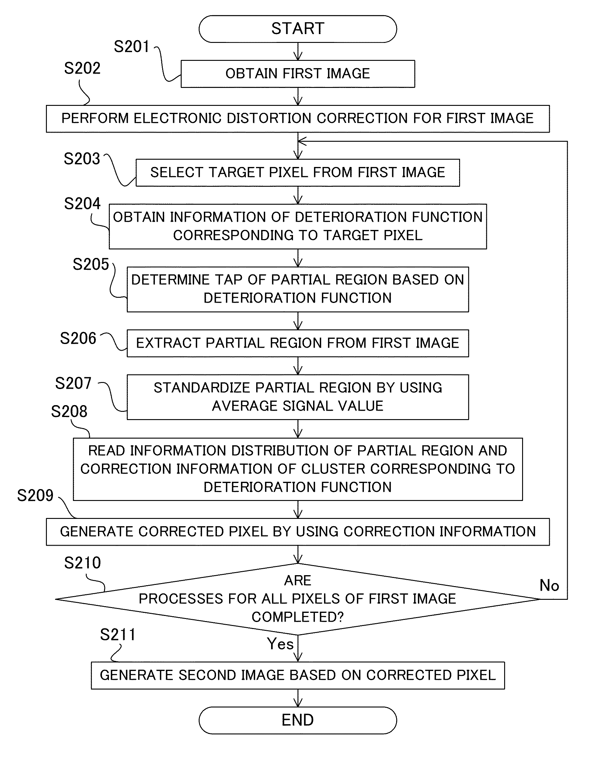
[0028]The image pickup apparatus 100 of the present embodiment is capable of performing an image processing method which includes a step (a first step) of obtaining correction information to be used to restore (recover) a frequency component lost due to aberration or diffraction, and a step (a second step) of performing image restoration processing by using the correction information. In the present embodiment, the first step is performed by a correction information calculating unit 104 of an image processing unit 103 (an ...

embodiment 2

(Embodiment 2)

[0099]Next, referring to FIGS. 9 and 10, Embodiment 2 of the present invention will be described. The present embodiment applies the image processing method of Embodiment 1 to an image processing system. FIG. 9 is a block diagram of an image processing system 200 in the present embodiment. FIG. 10 is an external view of the image processing system 200.

[0100]In FIGS. 9 and 10, an image processing apparatus 202 and a correction information calculating device 206 are a computer device which performs the image processing method of the present embodiment. The image processing apparatus 202 includes a communication unit 203. The communication unit 203 receives the first image (the shot image) from an image pickup apparatus 201. The communication unit 203 is connected to the correction information calculating device 206 via a network 207. This connection may be any of wired or wireless connection.

[0101]The correction information calculated in the correction information calcul...

embodiment 3

(Embodiment 3)

[0107]Next, referring to FIGS. 11 and 12, Embodiment 3 of the present invention will be described. The present embodiment applies the image processing method of Embodiment 1 to an image pickup system. FIG. 11 is a block diagram of an image pickup system 300 in the present embodiment. FIG. 12 is an external view of the image pickup system 300.

[0108]In FIGS. 11 and 12, a server 303 includes a communication unit 304, which is connected to an image pickup apparatus 301 via a network 302. This connection may be a wired or wireless connection. The connection unit 304 is configured to receive a first image (a shot image) from the image pickup apparatus 301. When the image pickup apparatus 301 shoots an image, the first image (the shot image) is automatically or manually inputted to the server 303, and then is sent to a storage unit 305 and an image processing unit 306. The storage unit 305 stores the first image and shooting condition information (information related to a sho...


PUM


Abstract

An image pickup apparatus (100) generates a second image based on a first image obtained via an image pickup optical system, and includes an image obtaining unit (101) configured to obtain the first image, a storage unit (106) configured to store a plurality of pieces of correction information calculated for each of groups divided based on information of a deteriorated image generated by applying each of a plurality of deterioration functions to a reference image and on the plurality of deterioration functions, and an image correcting unit (105) configured to generate the second image based on the first image by using correction information selected from among the plurality of pieces of correction information depending on information of the first image and the deterioration function based on shooting condition information.

Description

BACKGROUND OF THE INVENTION[0001]1. Field of the Invention[0002]The present invention relates to an image pickup apparatus which performs image restoration processing for a shot image.[0003]2. Description of the Related Art[0004]Recently, a high-quality shot image is desired along with a high-definition of a display device. However, the quality of the shot image is deteriorated due to an influence of aberration or diffraction by an optical system. On the other hand, a method of improving a quality of a shot image by applying an inverse filter for the deterioration such as a Wiener filter to the shot image (an image correcting method) is proposed. However, in the image correcting method of using the inverse filter, a frequency component in which an MTF (Modulation Transfer Function) is small cannot be restored.[0005]International Publication No. WO2007 / 074649 discloses a method of reducing the decrease of the MTF in a depth direction by inserting a phase modulation element into an op...

Claims


Application Information

Patent Timeline
Patent Type & Authority Patents(United States)
IPC IPC(8): H04N5/232H04N5/357
CPCH04N5/23248H04N5/3572H04N5/23229H04N23/80H04N25/61H04N23/68
Inventor HIASA, NORIHITO
Owner CANON KK
Learn More