
Actuating element for a telescopic sight

a technology of actuating elements and telescopic sights, applied in the field of actuators, can solve the problems of screw loss, relatively complicated procedure of loosening, turning and subsequently tightening screws, and the solution has some drawbacks

Inactive Publication Date: 2009-09-01
KAHLES M B H
View PDF19 Cites 23 Cited by
  • Summary
  • Abstract
  • Description
  • Claims
  • Application Information

AI Technical Summary

Benefits of technology

[0023]Due to the disconnectable coupling of the turret to the adjusting mechanism, the entire mechanics for activating and deactivating the limit stop can be integrated in the turret while maintaining full adjustability. In this way, contamination is prevented and no components can be lost. Adjustment and operation of the telescopic sight is made substantially easier due to the ability to set the actuator to different modes, with two of these serving to set up the basic settings and the third representing the actual “operating mode” in which the lead mark is brought into a position that corresponds to a particular shooting range by turning the rotary knob.
[0061]In order to reliably prevent any unintentional adjustment of an indexing element when turning the rotary knob, it is advantageous if the exterior surface of the indexing element is offset toward the axis of rotation of the rotary knob in relation to the lateral surface of the rotary knob.

Problems solved by technology

With such designs, however, it is usually only possible to index one specific setting, ie only one zero mark, for the point of impact for specific ballistics using a specific barrel for just one shooting range.
This solution, however, has some drawbacks in practice.
The procedure of loosening, turning, and subsequently tightening the screw is relatively complicated.
There is a risk of losing the screw.
In addition, the system can become contaminated with dirt relatively easily, which might lead to deterioration of the adjustability.

Method used


Image

  • Actuating element for a telescopic sight
  • Actuating element for a telescopic sight
  • Actuating element for a telescopic sight

Examples


Embodiment Construction

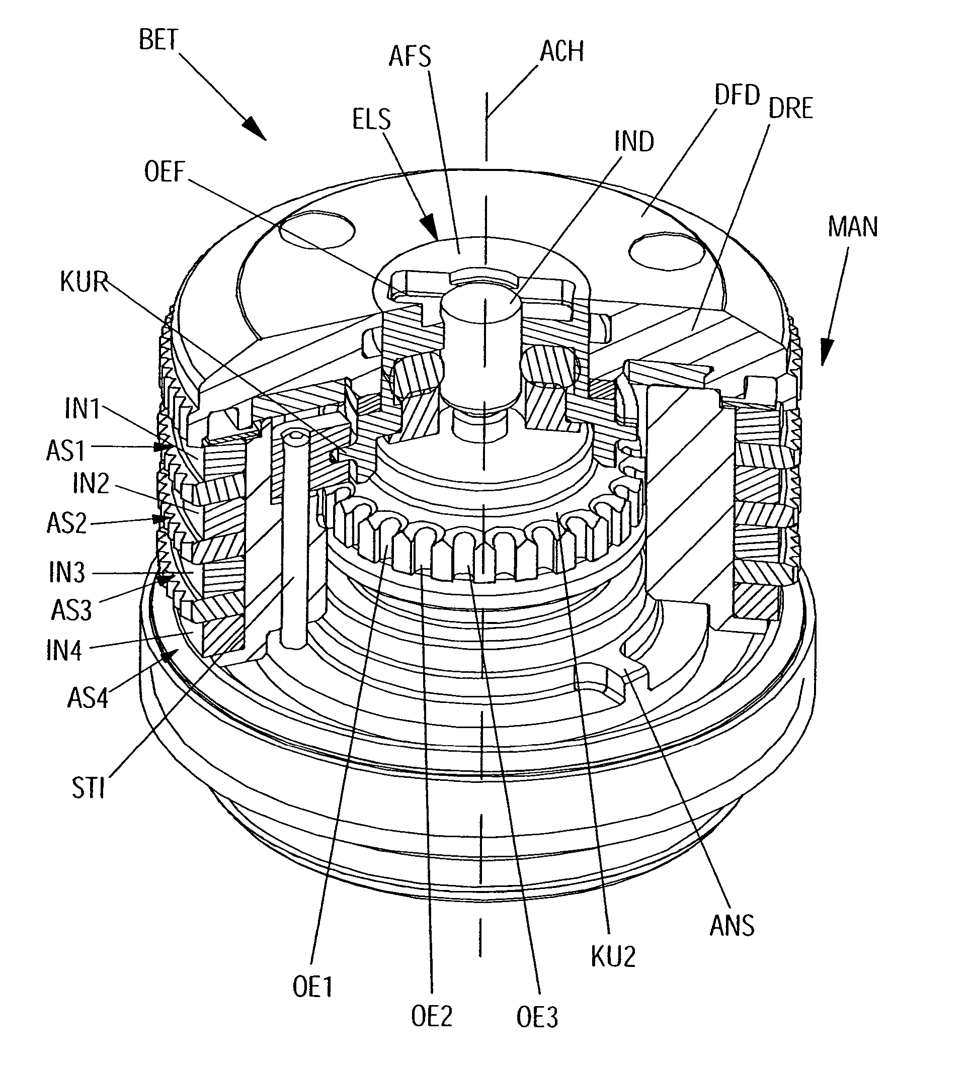
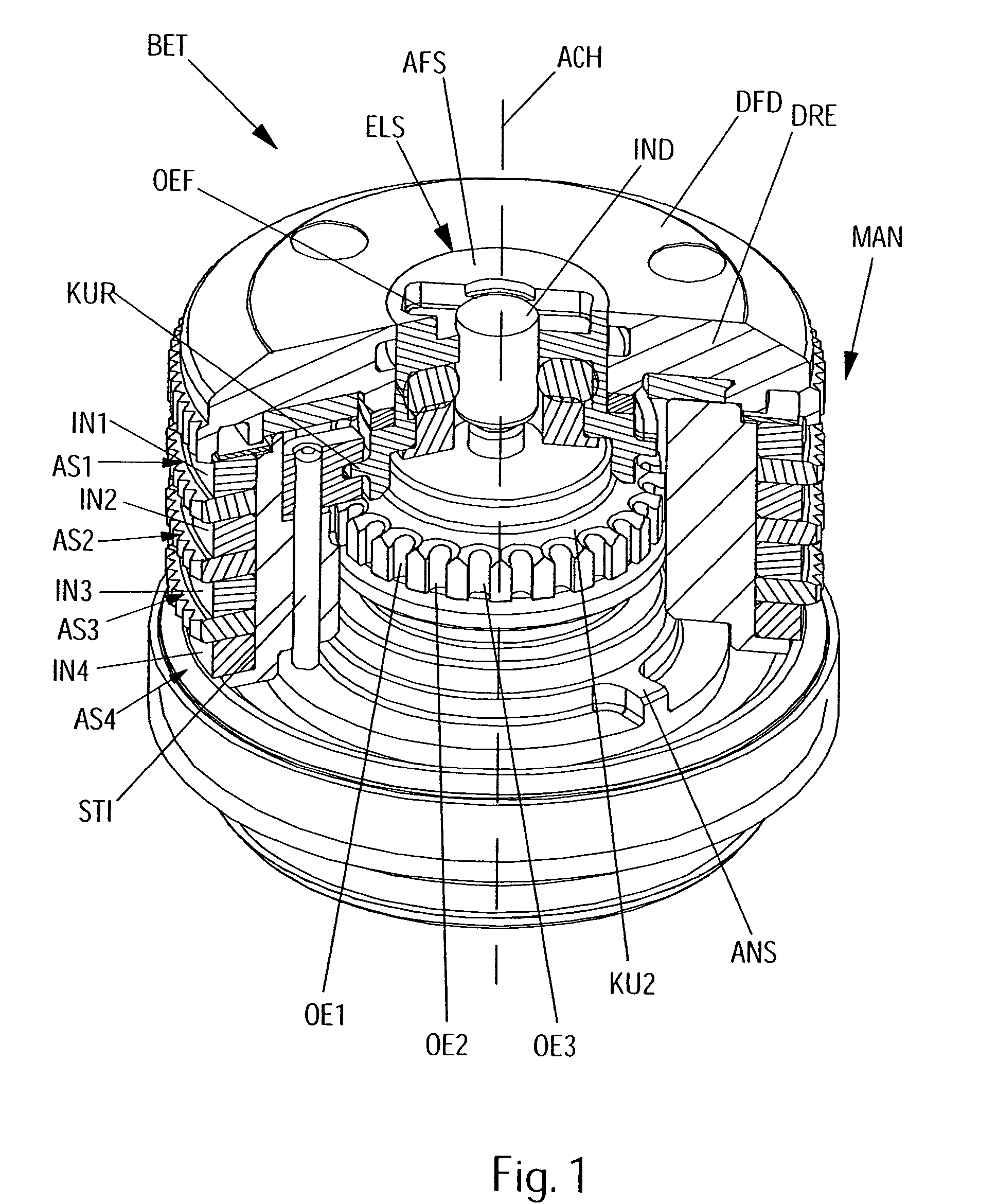
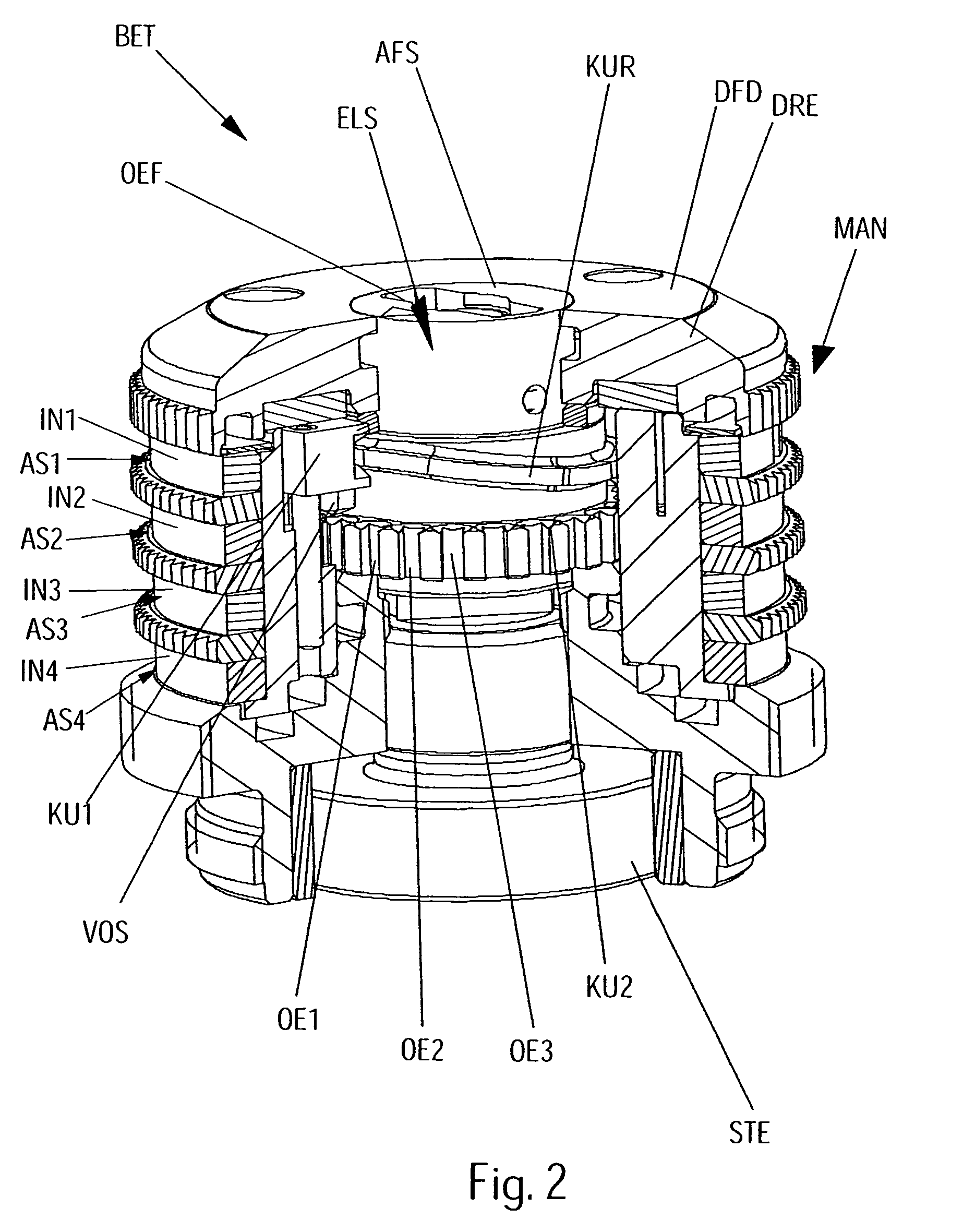
[0069]The invention described in this document relates to the positioning of a limit stop as well as to the definition of an adjustment range for a lead mark. Such adjustment, etc. is of particular advantage in connection with an actuator that permits indexing of the lead mark and, in particular, multiple indexing. The invention is therefore described below in more detail with reference to a specific actuator that permits multiple indexing. It may be pointed out, however, that the invention is also suitable for other actuators with multiple indexing or even for those that do not permit multiple indexing.

[0070]With the actuator shown, however, it is an advantage that the appropriate mechanism according to the invention can be particularly well accommodated in the rotary knob because of its special design.

[0071]The actuator BET shown consists, as can be seen in particular in FIGS. 1-4, in known manner, of, for instance, a rotary knob DRE that, when turned about its axis of rotation AC...


PUM


Abstract

The invention relates to an actuating element for setting the aim mark of a telescopic sight. According to the invention, the actuating element is rotatably located on the telescopic sight in the form of a rotary knob and the aim mark is displaced in a vertical and / or horizontal direction by means of a mechanical actuator, when the rotary knob is turned. In addition, the rotational area of the rotary knob is restricted in both rotational directions by at least one working region stop. The rotary knob is detachably coupled to the mechanical actuator. The working region stop(s) can be deactivated, allowing the rotary knob to be turned beyond the working region stop in both directions. The actuating element can be switched between at least three different modes. In mode A, the rotary knob is coupled to the mechanical actuator and the working region stop is inactive. In mode B, the rotary knob is decoupled from the mechanical actuator when the working region stop is active and in mode C, the rotary knob is coupled to the mechanical actuator and the working region stop is active.

Description

CROSS-REFERENCE TO RELATED APPLICATION[0001]This application is a U.S. National Stage application of PCT Application No. PCT / AT2005 / 000278, filed Jul. 18, 2005, which claims priority from Austrian Application No. A 1391 / 2004, filed on Aug. 18, 2004.FIELD OF THE INVENTION[0002]The invention relates to an actuator for adjusting the position of the lead mark of a telescopic sight, the actuator being in the form of a rotary knob mounted for rotation on the telescopic sight, rotation of said knob causing the lead mark to be adjusted by means of an adjusting mechanism in a vertical and / or horizontal direction while the turning range of the rotary knob is restricted by at least one operating range limit stop in both directions of rotation.BACKGROUND OF THE INVENTION[0003]Telescopic sights have a lead mark, for example in the form of a reticle. In order to be able to adjust the lead mark to the actual point of impact for specific ballistics (caliber, projectile mass, type of projectile, cha...

Claims


Application Information

Patent Timeline
IPC IPC(8): F41G1/38F41G1/00G02B23/00G02B27/36
CPCG02B23/00F41G1/38
Inventor KLEPP, CHRISTIANTHEISINGER, HERMANNWAGENSOMMERER, ROMAN
Owner KAHLES M B H
Learn More