Anchor plate mounting structure of vehicle seatbelt

a technology of mounting structure and seat belt, which is applied in the direction of belt anchoring devices, etc., to achieve the effect of increasing the amount of impact absorption of the lap belt and the amount of movement of the waist of the occupan

Active Publication Date: 2016-01-05
TOYOTA JIDOSHA KK
View PDF23 Cites 2 Cited by
  • Summary
  • Abstract
  • Description
  • Claims
  • Application Information

AI Technical Summary

Benefits of technology

[0007]The invention thus provides an anchor plate mounting structure of a vehicle seatbelt that increases an impact absorption amount by a lap belt, by inhibiting an amount of movement of the waist of an occupant when a vehicle collision occurs.
[0009]In this aspect, the anchor plate is fastened to the mounting portion at the fastening portion, and the lap belt is connected to the belt connecting portion of the anchor plate. The rotation-stopping portion that engages with the mounting portion side is provided in a position away from both the belt connecting portion and the fastening portion. The alignment direction of the belt connecting portion and the fastening portion intersects with the alignment direction of the fastening portion and the rotation-stopping portion. Therefore, when a load is input from the waist of the occupant to the anchor plate via the lap belt when a vehicle collision occurs, the anchor plate is inhibited from rotating around the fastening portion by the moment from this load. Therefore, the amount of movement of the waist of the occupant when a vehicle collision occurs is able to be suppressed, so the impact absorption amount by the lap belt is able to be increased.

Problems solved by technology

However, in the example described above, it is possible that an anchor plate may end up riding over the protruding bead due to a load input to the anchor plate at the time of a vehicle collision.

Method used


Image

  • Anchor plate mounting structure of vehicle seatbelt
  • Anchor plate mounting structure of vehicle seatbelt
  • Anchor plate mounting structure of vehicle seatbelt

Examples


first example embodiment

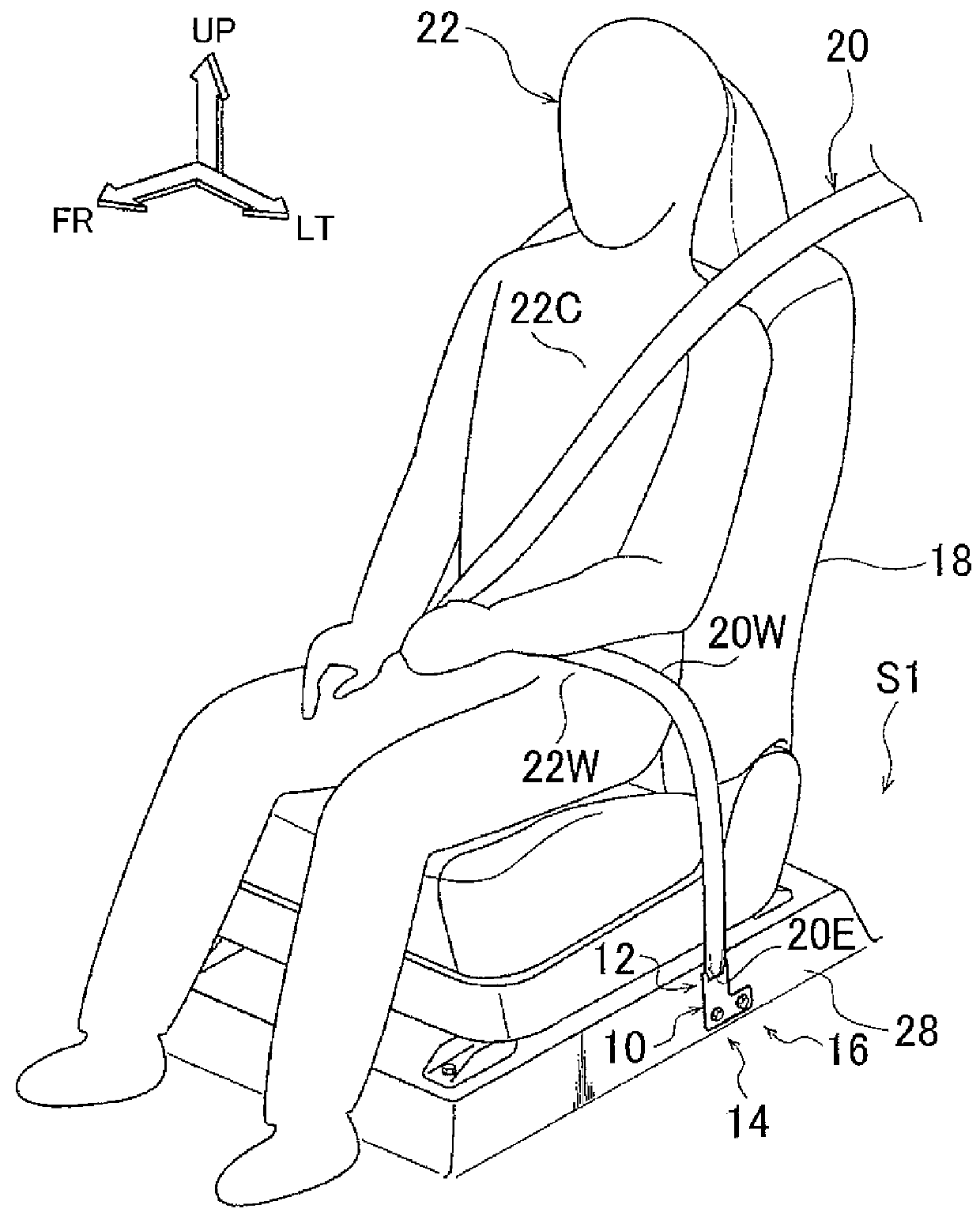
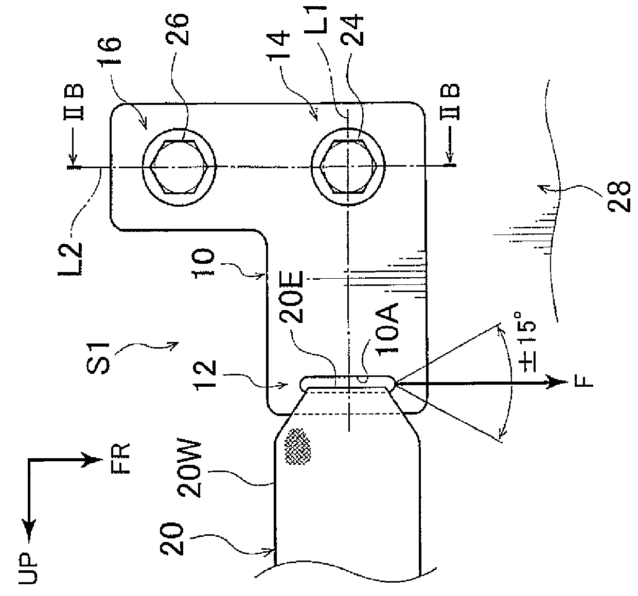
[0020]An anchor plate mounting structure S1 of a vehicle seatbelt according to a first example embodiment of the invention includes an anchor plate 10, a fastening portion 14, and a rotation-stopping portion 16, as shown in FIG. 1.

[0021]A vehicle seatbelt 20 is webbing that restrains a waist 22W and a chest 22C of an occupant 22 seated in a vehicle seat 18 (e.g., a rear seat). A portion of the vehicle seatbelt 20, more specifically, a portion from an end portion 20E that is connected to the anchor plate 10 to a tongue plate, not shown, is a lap belt 20W that corresponds to the waist 22W of the occupant 22. The length of the lap belt 20W changes depending on the physical build of the occupant 22 wearing the vehicle seatbelt 20. In the example shown in the drawings, the anchor plate 10 is provided on the left side of the vehicle seat 18, and a buckle device, not shown, is provided on the right side of the vehicle seat 18. The tongue plate is detachably inserted into this buckle device...

second example embodiment

[0033]With an anchor plate mounting structure S2 of a vehicle seatbelt according to a second example embodiment of the invention, the shaft member is a pin 30, as shown in FIGS. 4 and 5. In the example shown in FIG. 4B, the pin 30 is inserted through the through-hole 28C in the floor panel 28 and the through-hole 10C in the anchor plate 10 from the floor panel 28 side. The pin 30 may be fit into the through-hole 10C so that there is no gap between the pin 30 and the through-hole 10C. The pin 30 is a parallel pin, for example, and has a head portion 30A that is a large diameter portion. This head portion 30A abuts against the floor panel 28. The head portion 30A of the pin 30 is fixed to the floor panel 28 by welding or the like before the anchor plate 10 is attached to the floor panel 28.

[0034]On the other hand, in the example in FIG. 5B, the head portion 30A of the pin 30 is fixed to the anchor plate 10 by welding or the like before the anchor plate 10 is attached to the floor pane...


PUM


Abstract

An anchor plate mounting structure of a vehicle seatbelt includes an anchor plate that is provided on a mounting portion provided on a surrounding portion of a vehicle seat, and has a belt connecting portion to which an end portion of a lap belt of the vehicle seatbelt, the lap belt corresponding to a waist of an occupant, is fastened; a fastening portion that is provided in a position away from the belt connecting portion, and by which the anchor plate is fastened to the mounting portion; and a rotation-stopping portion that is provided in a position away from both the belt connecting portion and the fastening portion, and by which the anchor plate engages with a mounting portion side. An alignment direction of the belt connecting portion and the fastening portion intersects with an alignment direction of the fastening portion and the rotation-stopping portion.

Description

INCORPORATION BY REFERENCE[0001]The disclosure of Japanese Patent Application No. 2013-148767 filed on Jul. 17, 2013 including the specification, drawings and abstract is incorporated herein by reference in its entirety.BACKGROUND OF THE INVENTION[0002]1. Field of the Invention[0003]The invention relates to an anchor plate mounting structure of a vehicle seatbelt.[0004]2. Description of Related Art[0005]Japanese Patent Application Publication No. 10-203305 (JP 10-203305 A) describes a structure that stops a seatbelt anchor from rotating, by a protruding bead formed bent upward on a portion of a floor panel of a vehicle.[0006]However, in the example described above, it is possible that an anchor plate may end up riding over the protruding bead due to a load input to the anchor plate at the time of a vehicle collision. If the anchor plate rotates, the position of a connecting point on the anchor plate where a lap belt is connected will change. As a result, a load (tension) on the lap ...

Claims


Application Information

Patent Timeline
Patent Type & Authority Patents(United States)
IPC IPC(8): B60R22/26
CPCB60R22/26
Inventor HIRAKO, YUTAKA
Owner TOYOTA JIDOSHA KK
Why Eureka
Try Eureka